
Hydrothermal management integrated device of multi-stack fuel cell system and working method of hydrothermal management integrated device

A fuel cell system and integrated device technology, applied in fuel cells, fuel cell additives, electrolyte treatment of solid electrolyte cells, etc. and other problems to achieve the effect of improving stability

Active Publication Date: 2022-01-25
SHANGHAI CHONGSU ENERGY TECH CO LTD +1
View PDF5 Cites 2 Cited by
  • Summary
  • Abstract
  • Description
  • Claims
  • Application Information

AI Technical Summary

Problems solved by technology

The multi-stack fuel cell system has strong hydrothermal coupling and large hysteresis, and each fuel cell stack will have different heat production due to different aging degrees. It is also necessary to use coolant circulation to ensure uniform temperature of each single stack and prevent local hot spots. , affecting the performance of the multi-stack fuel cell system
Although there are already mature solutions for the single-stack water-heat management subsystem on the market, the current solution is not suitable for direct transplantation to multi-stack fuel cell systems from the perspective of structural design and cost.
In addition, when the existing water and heat management subsystem is applied to a multi-stack fuel cell system, it cannot solve the problem of slow start-up due to low coolant temperature during the start-up phase of the multi-stack fuel cell system, nor can it solve the problem of slow start-up due to cooling The conductive ions in the liquid affect the normal electrochemical reaction of the multi-stack fuel cell, which in turn leads to the problem of low operating stability of the multi-stack fuel cell system

Method used


Image

  • Hydrothermal management integrated device of multi-stack fuel cell system and working method of hydrothermal management integrated device
  • Hydrothermal management integrated device of multi-stack fuel cell system and working method of hydrothermal management integrated device
  • Hydrothermal management integrated device of multi-stack fuel cell system and working method of hydrothermal management integrated device

Examples


Embodiment Construction

[0045] The implementation of the present invention is illustrated by specific specific examples below, and those skilled in the art can easily understand other advantages and effects of the present invention from the content disclosed in this specification.

[0046]It should be noted that the structures, proportions, sizes, etc. shown in the drawings of this specification are only used to match the content disclosed in the specification, for those who are familiar with this technology to understand and read, and are not used to limit the conditions for the implementation of the present invention , so it has no technical substantive meaning, and any modification of structure, change of proportional relationship or adjustment of size shall still fall within the scope of the disclosure of the present invention without affecting the functions and objectives of the present invention. within the range covered by the technical content. At the same time, terms such as "upper", "lower"...


PUM


Abstract

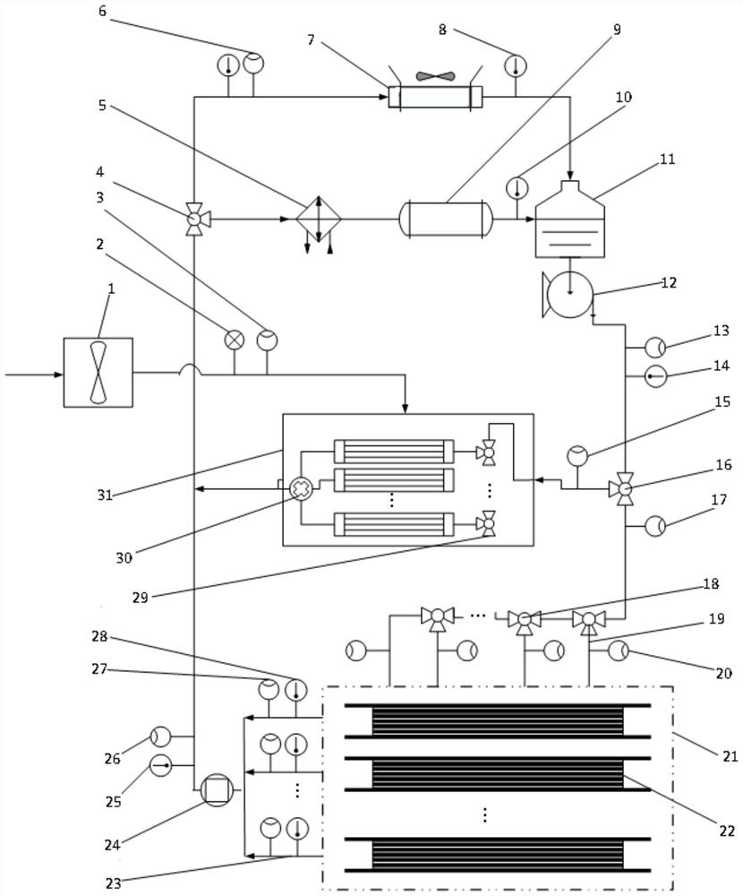
The invention provides a hydrothermal management integrated device of a multi-stack fuel cell system and a working method of the hydrothermal management integrated device. The hydrothermal management integrated device comprises a heat exchange unit, an air intercooling unit and a parallel cooling liquid pipeline unit; the heat exchange unit comprises a thermostat, a heater communicated with one flow channel valve opening of the thermostat, a radiator communicated with the other flow channel valve opening of the thermostat, a deionizer communicated with the heater, a water tank, a water pump connected with the water tank and a heat exchange bypass valve connected with the water pump, wherein the deionizer and the radiator are both communicated with the water tank; the parallel cooling liquid pipeline unit comprises in-stack cooling liquid pipelines and out-stack cooling liquid pipelines, and all the in-stack cooling liquid pipelines are respectively communicated with inlets of all single fuel cell stacks; and all the stack-out cooling liquid pipelines are respectively communicated with outlets of all the single fuel cell stacks. According to the hydrothermal management integrated device and the working method thereof, the starting speed and the operation stability of the multi-stack fuel cell system can be improved.

Description

technical field [0001] The invention relates to the technical field of fuel cells, in particular to a hydrothermal management integrated device for a multi-stack fuel cell system and a working method thereof. Background technique [0002] As an energy conversion device using hydrogen as fuel, proton exchange membrane fuel cells have the advantages of low operating temperature, high specific energy, fast start-up speed and long life, and have been widely used in many fields including automobile power sources. . Combining multiple single-stack fuel cells to form a multi-stack fuel cell system can not only increase the output power of the fuel cell system to meet high power requirements, but also increase the redundancy of the system output and improve the reliability of the system. [0003] The working process of the fuel cell is a heat production process, and its heat production is basically the same as the output power. Therefore, a thermal management subsystem needs to be ...

Claims


Application Information

Patent Timeline
Patent Type & Authority Applications(China)
IPC IPC(8): H01M8/04291H01M8/04029H01M8/04044H01M8/04225H01M8/249
CPCH01M8/04291H01M8/04029H01M8/04044H01M8/04225H01M8/249Y02E60/50
Inventor 周苏谢正春胡哲翟双
Owner SHANGHAI CHONGSU ENERGY TECH CO LTD
Learn More