


Quick Research
Generate reliable direction feasibility study reports for your R&D in just a few steps.

Technical Q&A
Discover and master advanced knowledge NOW. Basics, ideas, possibilities, all at once.

Find Solutions
As an expert in R&D theories, this can generate solutions to your technical problems instantly.

Evaluate Feasibility
Analyze your overall solution with one click, know your potential R&D risks in advance.

Monitor Landscape
Get weekly tech updates, stay abreast of the latest tech innovations and key insights.
Garbage crushing device for constructional engineering management
A technology of construction engineering and crushing device, which is applied in the field of construction engineering, can solve problems such as fracture, steel bar extrusion deformation, and increased cost of steel bar recycling, and achieve the effects of reducing investment, reducing safety hazards, and facilitating recycling
- Summary
- Abstract
- Description
- Claims
- Application Information
AI Technical Summary
Problems solved by technology
Method used
Image

Examples
Embodiment 1
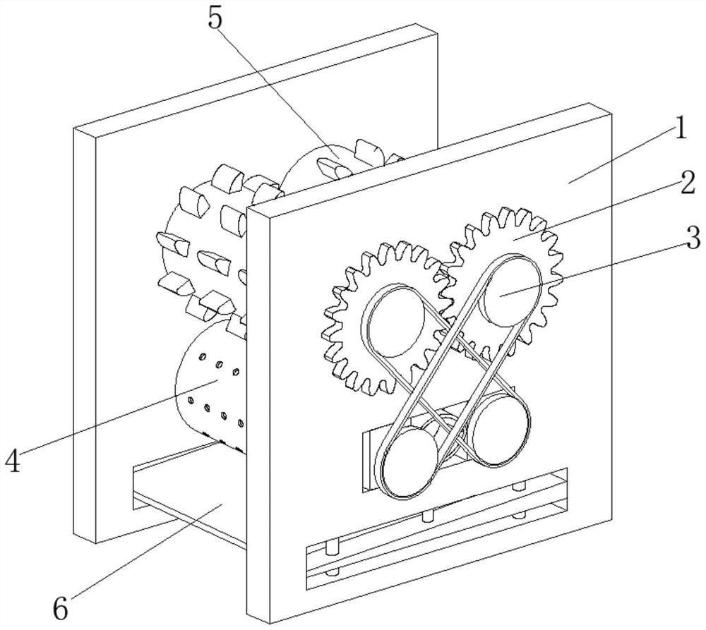
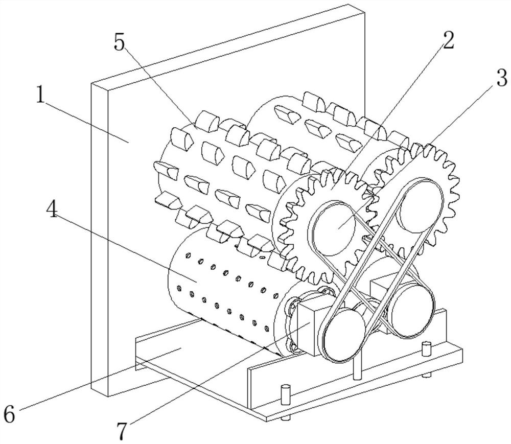
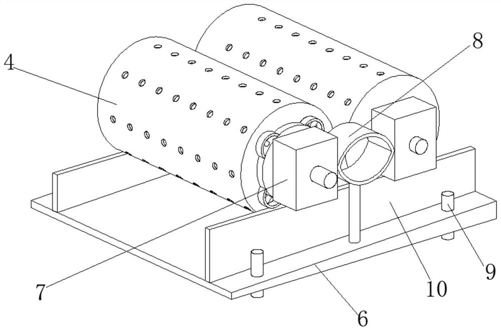
[0026] A garbage crushing device for construction engineering management, such as Figure 1-Figure 5 As shown, it includes a mounting plate 1, the right side of the mounting plate 1 is rotationally connected with a transmission gear 2, the axis of the transmission gear 2 is fixedly connected with a sprocket group 3, the left side of the mounting plate 1 is provided with a cleaning mechanism 4, and the mounting plate The left side of 1 is rotationally connected with a crushing roller 5, and the crushing roller 5 is located above the cleaning mechanism 4, and the inner wall of the mounting plate 1 is slidably connected with a swash plate 6 and a slider 7, and the slider 7 is located above the swash plate 6, The surface of the slider 7 is fixedly connected with an elastic member 8, the inner wall of the slant plate 6 is slidably connected with a guide post 9, the top of the slant plate 6 is fixedly connected with a limit plate 10, the inner wall of the transmission gear 2 is fixed...
Embodiment 2
[0032] Such as Figure 5-Figure 6 As shown, the surface of the transmission rod 43 is fixedly connected with an elastic plate 49, the surface of the elastic plate 49 is fixedly connected with a connecting plate 411 through a connecting rod, and the surface of the connecting plate 411 is fixedly connected with a support block 413, and the dust-proof net 47 can prevent inhalation The dust enters the airbag 48, and then causes the inside of the airbag 48 to be full of dust, thereby affecting the blowing volume of the airbag 48, causing the airbag 48 to use for a long time. The dust collection efficiency can be guaranteed all the time.
[0033] It is worth noting that the surface of the support block 413 is in contact with the inner wall of the pressure roller 41, the two sides of the connecting plate 411 are slidingly connected with the inner wall of the pressure roller 41, and the inside of the elastic plate 49 is provided with a diamond-shaped hole. The design of the diamond-sh...
PUM
 Abstract
Description
Claims
Application Information
 - R&D Engineer
- R&D Manager
- IP Professional
- Industry Leading Data Capabilities
- Powerful AI technology
- Patent DNA Extraction
Browse by: Latest US Patents, China's latest patents, Technical Efficacy Thesaurus, Application Domain, Technology Topic, Popular Technical Reports.
© 2024 PatSnap. All rights reserved.Legal|Privacy policy|Modern Slavery Act Transparency Statement|Sitemap|About US| Contact US: help@patsnap.com