
Quick mounting building and mounting method thereof

A construction and quick installation technology, applied in the direction of construction, building components, building structure, etc., can solve the problems of self-heavy components, poor seismic resistance, and difficult assembly, and achieve strong node support, fast and stable connection, and installation speed. quick effect

Pending Publication Date: 2022-01-14
刘旭
View PDF0 Cites 0 Cited by
  • Summary
  • Abstract
  • Description
  • Claims
  • Application Information

AI Technical Summary

Problems solved by technology

[0002] In the construction of traditional concrete buildings, a large amount of high-energy building materials such as sand and cement are used, which cannot be recycled after reaching the end of their service life, causing a great burden to the ecological environment
In traditional steel structure buildings, the steel structure mainly plays the role of frame support, and the frame still needs to be filled with walls, resulting in high overall cost and high energy consumption
The traditional concrete building concrete material is relatively brittle, and it is easy to collapse in the event of a strong earthquake, posing a threat to life and property
[0003] In traditional steel structure buildings, the steel structure is used as a load-bearing frame. There is no brace in the middle of the steel structure, which has poor stability and poor earthquake resistance.
Although traditional steel structural parts are produced in factories, they are still mainly welded and cannot be produced in an assembly line.
Traditional concrete prefabricated buildings and steel structure prefabricated buildings have heavy components and difficult assembly

Method used


Image

  • Quick mounting building and mounting method thereof
  • Quick mounting building and mounting method thereof
  • Quick mounting building and mounting method thereof

Examples


Embodiment 1

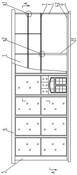
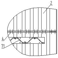
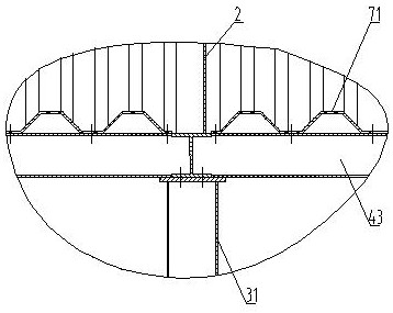
[0043] Such as figure 1 , figure 2 , image 3 , Figure 4 As shown, the composition of the quick-installation building of the present invention includes: a quick-installation wallboard 1, the quick-installation wallboard 1 includes a corrugated board 2, the two sides of the corrugated board are bent to form a connecting column 3, and the described The upper end and the lower end of the corrugated plate have end beams 4 or the upper and lower ends of the corrugated plate are connected with beams 41 . The horizontally adjacent quick-install wall panels 1 are assembled and connected by the connecting column during installation. The cross-section of the connecting column is groove-shaped, and the three sides of the groove-shaped connecting column are combined to form a linear wall. 51 or L-shaped body of wall 52 or T-shaped body of wall 53 or cross-shaped body of wall 54, after being assembled and connected together constitute building wall body 5, the design of groove-shaped ...

Embodiment 2

[0045] In the quick-installation building described in Embodiment 1, the quick-installation wallboard is a plane quick-installation wallboard, a right-angle quick-installation wallboard 11 or an arc-shaped quick-installation wallboard, and the middle part of the corrugated board is bent to form the Right-angle quick-loading wall panels 11. Such as Figure 5 , Figure 9 The adjacent planar quick-install wallboards shown are horizontally connected to form a linear wall body 51 .

Embodiment 3

[0047] The fast-packing building described in embodiment 1 or 2, such as Figure 5 , Figure 6 Figure 7 , Figure 8 , Figure 10 As shown, different wall parts are formed by different combinations of three sides of the groove-shaped connecting column, and the four adjacent quick-installed wall panels 1 are assembled and connected by the connecting column 3 to form the cross-shaped The wall 54, or the two flat quick-install wall panels and one right-angle quick-install wall panel 11 are connected by the right-angle side formed by bending the right-angle quick-install wall panel 11 through the connecting column 3 Body columns are assembled and connected to form the cross-shaped wall; three right-angled adjacent quick-install wall panels 1 are assembled and connected through the connecting column 3 to form the T-shaped wall, or one of the The plane quick-installation wallboard and one of the right-angle quick-installation wallboards are assembled and connected by the right-a...


PUM


Abstract

The invention relates to a quick mounting building and a mounting method thereof. According to a traditional steel structure building, a steel structure is used as a force bearing frame, welding is mainly adopted, and assembly line production cannot be achieved. A traditional prefabricated concrete building and a prefabricated steel structure building have the defects of large component dead weight and large assembly difficulty. The quick mounting building comprises quick mounting wallboards, wherein the quick mounting wallboards include corrugated plates / groove plates, the two side edges of the corrugated plates / groove plates are bent to form connecting columns, the upper ends and the lower ends of the corrugated plates / groove plates are provided with end beams or the upper ends and the lower ends of the corrugated plates / groove plates are connected with cross beams, the horizontal adjacent quick mounting wallboards are assembled and connected through the connecting columns to form a linear wall body or an L-shaped wall body or a T-shaped wall body or a cross-shaped wall body, and a building wall body is jointly formed after the quick mounting wallboards are assembled and connected; the end beams or the cross beams which are located on the top of the building wall body are connected with a roof; the end beams or the cross beams which are located at the bottom of the building wall body are connected with a foundation or are connected with the foundation through base beams; and the quick mounting building comprises doors and windows, and a heat preservation and insulation layer is installed on the peripheral building wall body.

Description

technical field [0001] The invention belongs to the technical field of structural engineering, and relates to a low-rise building with low energy consumption and fast installation. It is suitable for the construction of low-rise buildings, exhibition halls, villas, temporary hospitals, field barracks, etc. Background technique [0002] In the construction of traditional concrete buildings, a large amount of high-energy-consuming building materials such as sand and cement are used, which cannot be recycled after reaching the end of their service life, causing a great burden on the ecological environment. In traditional steel structure buildings, the steel structure mainly plays the role of frame support, and walls still need to be filled in the frame, resulting in high overall cost and high energy consumption. The traditional concrete building concrete material is relatively brittle, and it is easy to collapse in the event of a strong earthquake, posing a threat to life and ...

Claims


Application Information

Patent Timeline
Patent Type & Authority Applications(China)
IPC IPC(8): E04B1/00E04B2/56E04C2/32E04B1/38E04B1/76E04B1/61E04G21/14E02D27/12E04C3/04E04B5/00E04B1/58
CPCE04B1/00E04B2/56E04C2/32E04B1/38E04B1/76E04B1/61E04G21/14E02D27/12E04C3/04E04B5/00E04B1/58
Inventor 刘旭
Owner 刘旭
Learn More