


Quick Research
Generate reliable direction feasibility study reports for your R&D in just a few steps.

Technical Q&A
Discover and master advanced knowledge NOW. Basics, ideas, possibilities, all at once.

Find Solutions
As an expert in R&D theories, this can generate solutions to your technical problems instantly.

Evaluate Feasibility
Analyze your overall solution with one click, know your potential R&D risks in advance.

Monitor Landscape
Get weekly tech updates, stay abreast of the latest tech innovations and key insights.
Two-piece type ceramic ball valve
A ceramic ball valve, two-piece technology, applied in the direction of the valve device, valve details, valve shell structure, etc., can solve the problems of reducing the service life and stability of the pipeline, increasing the cost of pipeline monitoring, increasing harmful impacts, etc., to eliminate safety hidden dangers, reduce monitoring costs, and ensure normal work
- Summary
- Abstract
- Description
- Claims
- Application Information
AI Technical Summary
Problems solved by technology
Method used
Image

Examples
specific Embodiment approach
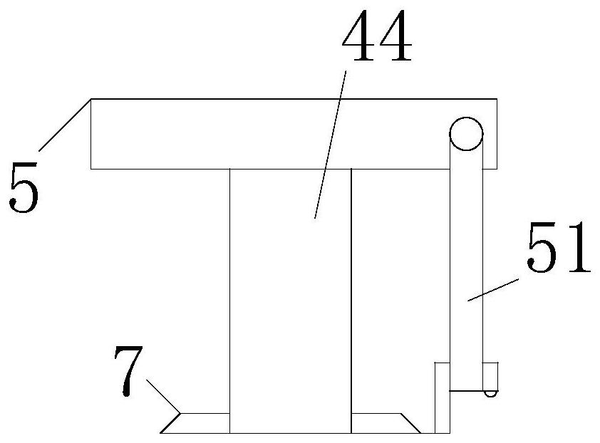
[0026] As a specific embodiment of the present invention, the bottom of the installation groove 241 is provided with a No. 2 sealing port 242; the No. 2 bracket 24 is provided with a restraint device 4 corresponding to the installation groove 241; the restraint device 4 includes a T-shaped bar 41 and helical gear; the T-end of the T-shaped rod 41 is inserted in the spring 3; the other end of the T-shaped rod 41 passes through the second sealing port 242 and is fixedly connected to the No. 1 bevel gear 42; the No. 1 cone The gear 42 meshes with the No. 2 bevel gear 3; the inner surface of the No. 2 bevel gear 3 is fixedly connected to the transmission rod 44; the transmission rod 44 runs through the No. 2 cavity 243 inside the No. The knob 5 on the surface is fixedly connected;
[0027] After the outer net 21 leaving the surface of No. 2 bracket 24 finishes absorbing the impact force brought by the liquid water hammer effect, the knob 5 on the upper surface of No. 2 bracket 24 ...
Embodiment approach
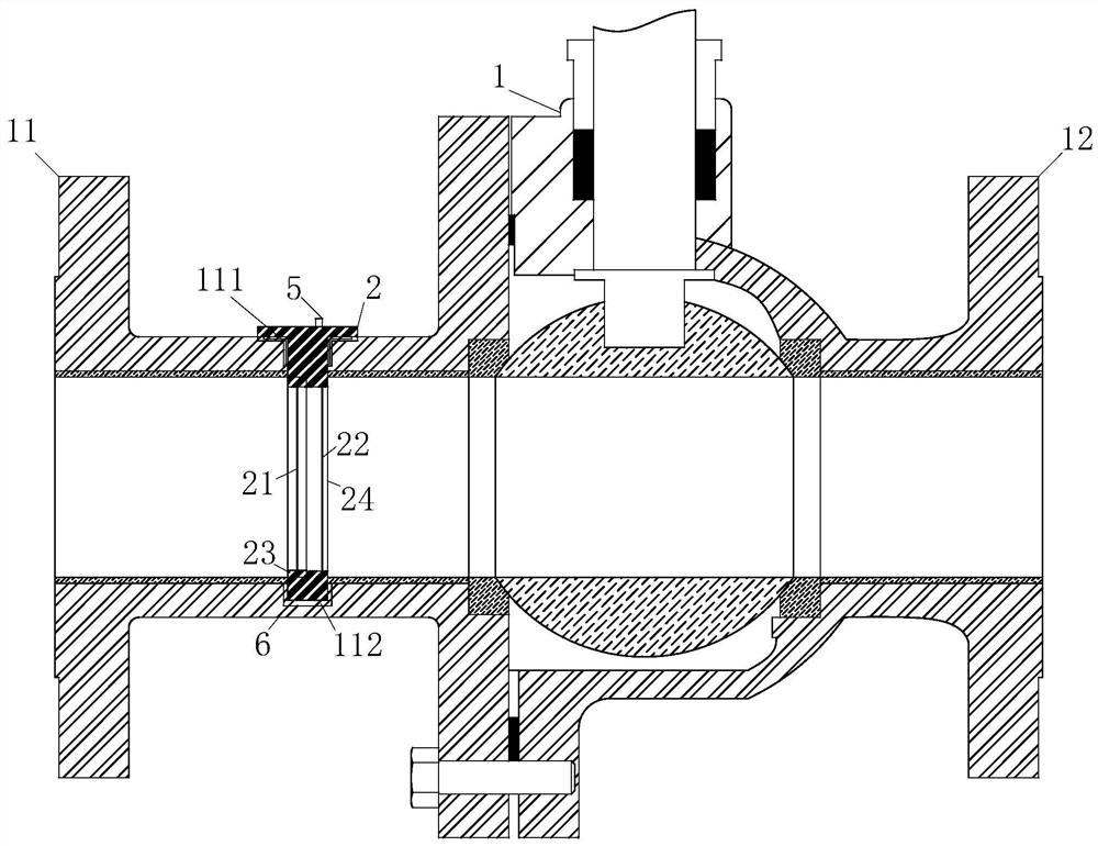
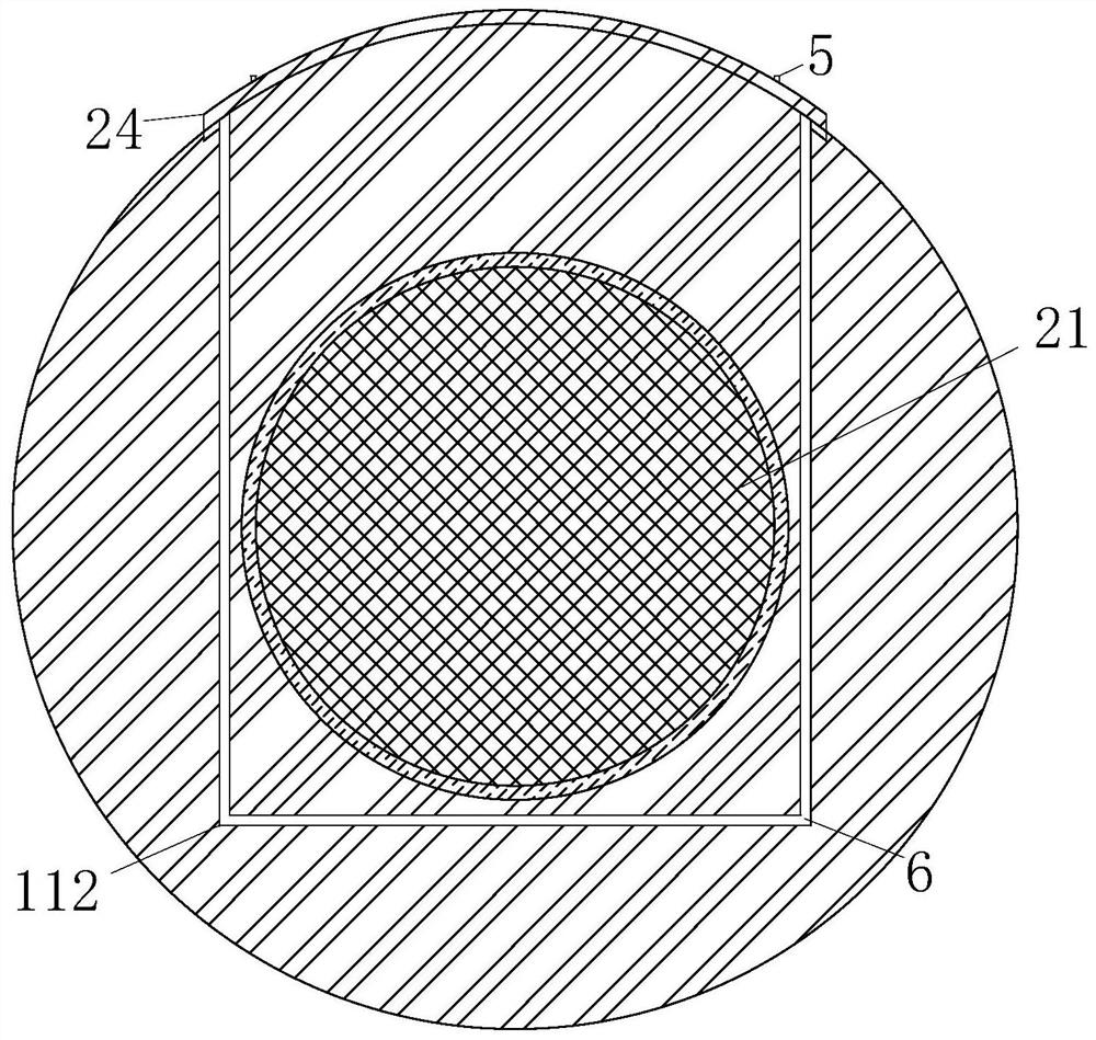
[0034] As a specific embodiment of the present invention, a sealing sleeve 6 is provided at the joint between the No. 1 cavity 112 inside the left valve body 11 and the buffer device 2; a sealing gasket is provided at the fixed connection between the transmission rod 44 and the knob 5 7;
[0035] The setting of the sealing sleeve 6 and the sealing gasket 7 can ensure that the buffer device 2 prevents medium leakage when inserted into the pipeline of the left valve body 11, and ensures that the ball valve will not affect the normal use of the ball valve due to insufficient sealing performance.
[0036] Working principle: A buffer device 2 composed of a double-layer net is inserted in the ball valve pipeline. The net structure can not only disperse the pressure of the liquid impact, but also block and filter some impurities during the normal operation of the ball valve. The design of the double-layer net not only The structural strength of the buffer device 2 can be improved, an...
PUM
 Abstract
Description
Claims
Application Information
 - R&D Engineer
- R&D Manager
- IP Professional
- Industry Leading Data Capabilities
- Powerful AI technology
- Patent DNA Extraction
Browse by: Latest US Patents, China's latest patents, Technical Efficacy Thesaurus, Application Domain, Technology Topic, Popular Technical Reports.
© 2024 PatSnap. All rights reserved.Legal|Privacy policy|Modern Slavery Act Transparency Statement|Sitemap|About US| Contact US: help@patsnap.com