Tunneling device and method suitable for soft rock stratum

A technology of tunneling and formation, which is applied in the direction of tunneling, earthwork drilling, cutting machinery, etc. It can solve the problems of poor health of construction workers, slow excavation speed and consumption, and dust pollution of the environment, so as to save manpower and material resources and speed up excavation progress , the effect of reducing the amount of dust

Pending Publication Date: 2021-12-28
SHANDONG UNIV
View PDF5 Cites 0 Cited by
  • Summary
  • Abstract
  • Description
  • Claims
  • Application Information

AI Technical Summary

Problems solved by technology

[0004] The inventor found that tunnels in soft rock formations are usually excavated by excavators and transported by slag trucks. However, this method is extensive and cannot be quantified. It is easy to produce a large amount of dust to pollute the environment and also cause adverse effects on the health of construction workers.

Method used


Image

  • Tunneling device and method suitable for soft rock stratum
  • Tunneling device and method suitable for soft rock stratum
  • Tunneling device and method suitable for soft rock stratum

Examples


Embodiment 1

[0038] Embodiment 1 of the present invention provides a tunnel excavation device suitable for soft rock formations, including: a transmission mechanism, a blade type excavation mechanism and a hydraulic propulsion mechanism;

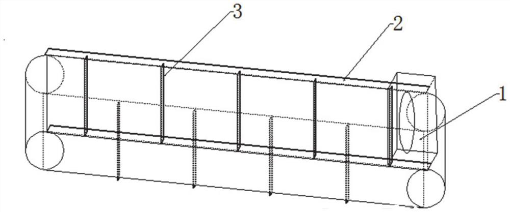
[0039] Such as figure 1 As shown, there are protrusions 3 on the conveyor belt of the transmission mechanism, and there are baffles 2 on the left and right, and there is a soil collecting device 1 at the end. The way of splicing and connecting is that the previous conveyor belt slag transporting device transports the slag to the top of the next conveyor belt slag transporting device and pours the slag into the soil collecting device 1 of the next conveyor belt slag transporting device.

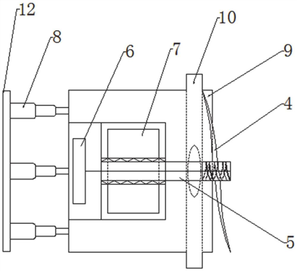
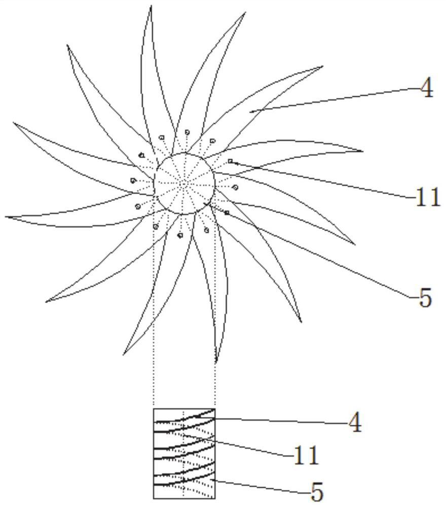
[0040] Such as figure 2 As shown, the blade type excavating device includes a screw blade mechanism 4, a transmission shaft 5, a high-pressure water pump 6, a water collecting device 9 and an excavation port 10, and the hydraulic propulsion mechanism includes a reactio...

Embodiment 2

[0049] Embodiment 2 of the present invention provides a method suitable for tunneling in soft rock formations, comprising the following steps:

[0050] Step 1: Determine the location of the excavation, and place the blade type excavation device and the reaction support at the designated location;

[0051] Step 2: According to the footage length of the tunnel, estimate the number of conveyor belt slag transport devices and place the conveyor belt slag transport devices at designated locations;

[0052] Step 3: Start the motor to drive the blades to cut the soil, and at the same time, the water outlet hole is sprayed to the excavated soil to realize automatic mechanized excavation, and the soil falls into the spliced ​​conveyor belt through the excavation port to realize automatic slag discharge.


PUM


Abstract

The invention provides a tunneling device and method suitable for a soft rock stratum. The tunneling device comprises a conveying mechanism, a blade type tunneling mechanism and a hydraulic propelling mechanism. The conveying mechanism is arranged below the blade type tunneling mechanism and used for conveying muck generated by tunneling, and the hydraulic propelling mechanism is connected with the blade type tunneling mechanism and used for controlling stretching and retracting of the blade type tunneling mechanism; and the blade type tunneling mechanism at least comprises a blade device, a transmission shaft and a water pump, the blade device is connected with a rotating motor through the transmission shaft, a water conveying pipeline is arranged in a hollow structure of the transmission shaft, one end of the water conveying pipeline communicates with a water outlet of a spiral blade mechanism, the other end of the water conveying pipeline communicates with a water outlet of the water pump, and a water collecting device is arranged at the bottom of the blade device. The construction method of a traditional soft rock stratum tunnel is improved, automation of tunneling is achieved, and a large amount of manpower and material resources are saved; the excavation progress of the tunnel is accelerated, and the engineering time is saved; and the dust amount is reduced, and the environmental pollution is reduced.

Description

technical field [0001] The invention relates to the technical field of tunnel excavation, in particular to a tunnel excavation device and method suitable for soft rock formations. Background technique [0002] The statements in this section merely provide background art related to the present invention and do not necessarily constitute prior art. [0003] At present, traffic construction shows a development trend from plain hills to heavy hills, and the number of long tunnels under various complex and harsh geological conditions has also increased sharply. In some areas, the unique soft rock geology is mostly silty mudstone, strongly weathered rock formations, extremely soft, extremely low compressive strength, poor cohesion, extremely unstable, and the water strength is greatly reduced. [0004] The inventor found that tunnels in soft rock formations are usually excavated by excavators and transported by slag trucks. However, this method is extensive and cannot be quantifi...

Claims


Application Information

Patent Timeline
Patent Type & Authority Applications(China)
IPC IPC(8): E21D9/10E21D9/12E21C35/23
CPCE21D9/1006E21D9/1086E21D9/1093E21D9/12E21C35/23
Inventor 赵勇郭伟东刘进佩路杰李咸森卜林赵瑞杰石少帅
Owner SHANDONG UNIV
Why Eureka
Try Eureka