Energy-saving boiler

An energy-saving, boiler technology, applied in the direction of steam boilers, steam boiler accessories, steam boiler components, etc., can solve the problems of steam slump, fuel waste, affecting the boiling point of water, etc., to improve the heat exchange time and prolong the movement. path, the effect of improving the thermal insulation effect

Inactive Publication Date: 2021-12-24
余帆
View PDF0 Cites 0 Cited by
  • Summary
  • Abstract
  • Description
  • Claims
  • Application Information

AI Technical Summary

Problems solved by technology

The structure of the water storage cavity of the existing boiler is not reasonable enough. When the water temperature is low in winter, when the boiler is supplemented with water, the water temperature will inevitably drop, resulting in a sudden drop of steam, which will affect the continuous gas supply
When the water vapor produced by the boiler is out of balance with the water vapor used, the pressure inside the water storage chamber will change, thereby affecting the boiling point of water and easily causing waste of fuel

Method used


Image

  • Energy-saving boiler
  • Energy-saving boiler
  • Energy-saving boiler

Examples


Embodiment Construction

[0029] The following will clearly and completely describe the technical solutions in the embodiments of the present invention with reference to the accompanying drawings in the embodiments of the present invention. Obviously, the described embodiments are only some, not all, embodiments of the present invention. Based on the embodiments of the present invention, all other embodiments obtained by persons of ordinary skill in the art without creative efforts fall within the protection scope of the present invention.

[0030] In describing the present invention, it is to be understood that the terms "opening", "upper", "lower", "thickness", "top", "middle", "length", "inner", "surrounding" etc. Indicating orientation or positional relationship is only for the convenience of describing the present invention and simplifying the description, and does not indicate or imply that the components or elements referred to must have a specific orientation, be constructed and operated in a sp...


PUM


Abstract

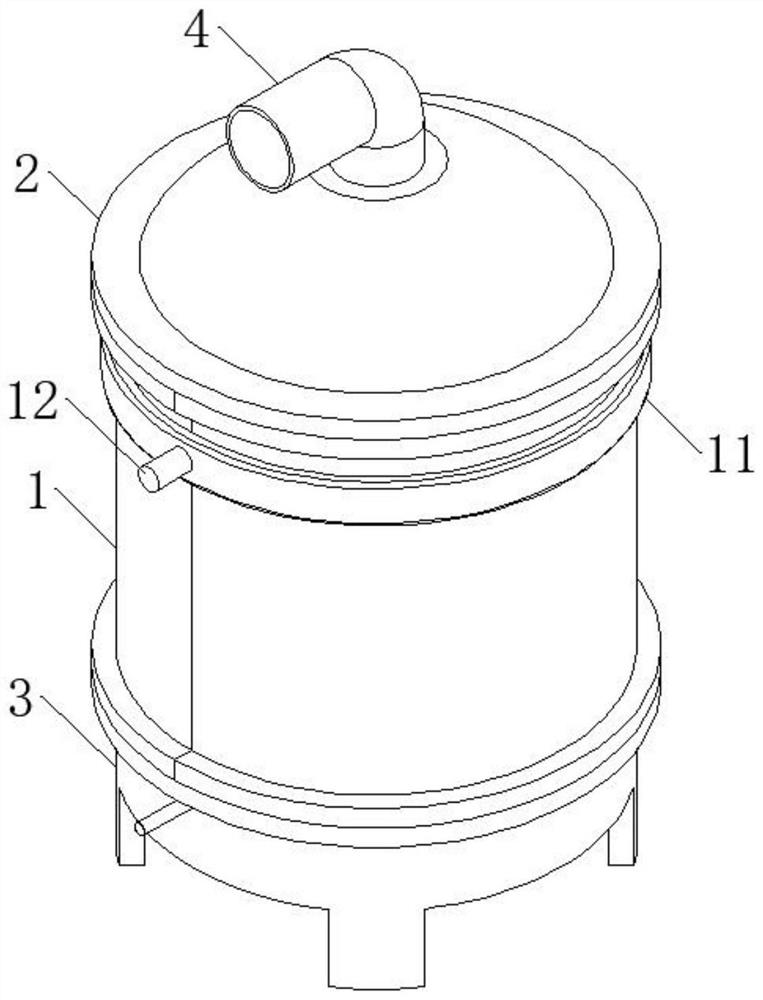
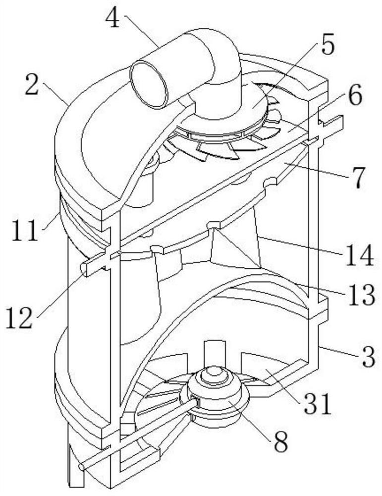
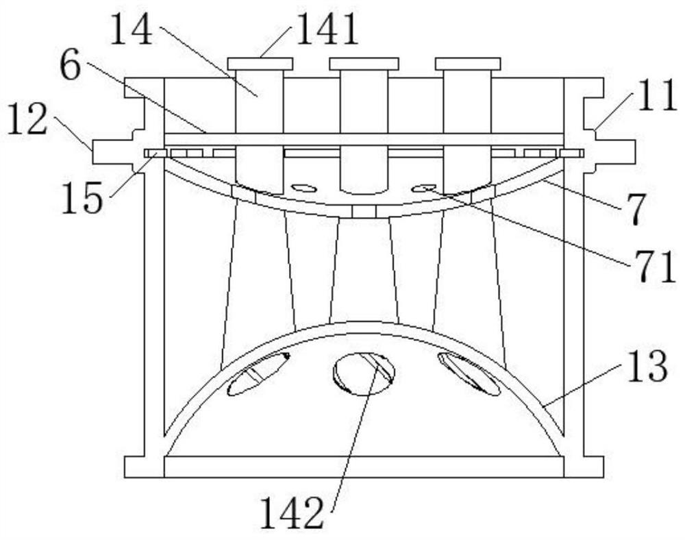
The invention discloses an energy-saving boiler, and relates to the technical field of boiler equipment. The energy-saving boiler comprises a shell, a cover body is cooperatively installed at the top end of the shell, a base is cooperatively installed at the bottom end of the shell, a smoke exhaust pipe is installed on the cover body, a drainage part is installed at the air inlet end of the smoke exhaust pipe, a combustor is installed on the bottom surface of the base, a first partition plate and a movable plate are installed in the shell, the first partition plate is located on the lower side of the movable plate, a combustion chamber is formed between the first partition plate and the base, a smoke exhaust chamber is formed between the movable plate and the cover body, a water storage chamber is formed between the first partition plate and the movable plate, the first partition plate is connected to the movable plate through a plurality of through pipes penetrating through the water storage chamber, and meanwhile the combustion chamber communicates with the smoke exhaust chamber through a plurality of through pipes. According to the energy-saving boiler, the smoke exhaust chamber and the water storage chamber are separated through the movable plate, heat of generated smoke is transferred to water vapor gathered at the top of the water storage chamber through the movable plate, and the situation that after being condensed and liquefied, the water vapor enters a connecting pipe, and consequently a pipeline is blocked is avoided.

Description

technical field [0001] The invention belongs to the technical field of boiler equipment, in particular to an energy-saving boiler. Background technique [0002] There are many types of existing boilers, and whether energy saving is considered two factors, one is sufficient combustion, and the other is heat exchange efficiency. The structure of the existing boiler water storage chamber is not reasonable enough. When the water temperature is low in winter and the boiler is supplemented with water, the water temperature will inevitably drop, resulting in a sudden drop of steam and affecting the continuous gas supply. When the water vapor produced by the boiler is out of balance with the water vapor used, the pressure inside the water storage chamber will change, thereby affecting the boiling point of water and easily causing waste of fuel. Contents of the invention [0003] The object of the present invention is to provide an energy-saving boiler. The burner installed in the...

Claims


Application Information

Patent Timeline
IPC IPC(8): F22B31/00F22B31/08F22B37/00
CPCF22B31/00F22B31/08F22B37/00
Inventor 余帆
Owner 余帆
Why Eureka
Try Eureka