


Quick Research
Generate reliable direction feasibility study reports for your R&D in just a few steps.

Technical Q&A
Discover and master advanced knowledge NOW. Basics, ideas, possibilities, all at once.

Find Solutions
As an expert in R&D theories, this can generate solutions to your technical problems instantly.

Evaluate Feasibility
Analyze your overall solution with one click, know your potential R&D risks in advance.

Monitor Landscape
Get weekly tech updates, stay abreast of the latest tech innovations and key insights.
Suspension bridge main cable composite dehumidification system for recovering condensation heat through separated heat pipes
A separate heat pipe and suspension bridge technology, applied in the field of dehumidification of bridges, can solve problems such as poor dehumidification effect, high energy consumption in operation, and poor environmental adaptability, etc., and achieve reduced energy consumption of regenerative electric heating, strong environmental adaptability, and energy saving Obvious effect
- Summary
- Abstract
- Description
- Claims
- Application Information
AI Technical Summary
Problems solved by technology
Method used
Image

Examples
Embodiment 1
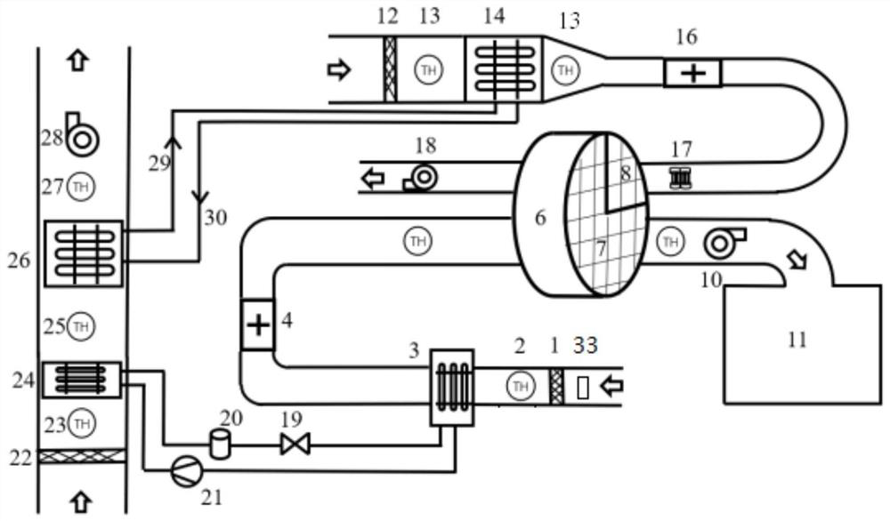
[0029] Such as figure 1 As shown, the suspension bridge main cable composite dehumidification system using separate heat pipes to recover condensation heat includes: dehumidification runner 6, wet air treatment system, regeneration air system and condensation heat recovery system.
[0030] The dehumidification rotor 6 is used to provide dry air to the main cable of the suspension bridge, and the dehumidification rotor includes a treatment area 7 and a regeneration area 8 .
[0031] The wet air treatment system is used to cool and condense the humid air entering the dehumidification wheel treatment area 7. The wet air treatment system includes an evaporator 3, a compressor 21 and a condenser 24 connected in sequence, and the condensate outlet of the condenser is connected to the evaporation The condensate inlet of the evaporator, the water vapor outlet of the evaporator 3 is connected to the compressor 21, and the compressor 21 is connected to the steam inlet of the condenser 2...
Embodiment 2
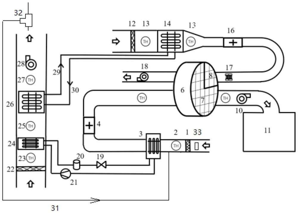
[0044] Such as figure 2 As shown, the difference between this embodiment and Embodiment 1 is that the condensation heat recovery system is connected to the air inlet of the humid air treatment system through a bypass line 31 to provide low-temperature and low-humidity air for the humid air treatment system. The air in the condensation heat recovery system is cooled and condensed by the separate heat pipe evaporation section 26 to form low-temperature and low-humidity air, and the fan 28 supplies the low-temperature and low-humidity air discharged from the condensation heat recovery system to the humid air treatment system, reducing the impact of the wet air treatment system on the air. Cooling capacity required for condensation and dehumidification.
[0045] A first three-way valve 32 is installed on the bypass pipeline 31 , and the bypass pipeline 31 is connected in parallel on the pipeline between the first temperature and humidity sensor 2 and the evaporator 3 . The upstr...
PUM
 Abstract
Description
Claims
Application Information
 - R&D Engineer
- R&D Manager
- IP Professional
- Industry Leading Data Capabilities
- Powerful AI technology
- Patent DNA Extraction
Browse by: Latest US Patents, China's latest patents, Technical Efficacy Thesaurus, Application Domain, Technology Topic, Popular Technical Reports.
© 2024 PatSnap. All rights reserved.Legal|Privacy policy|Modern Slavery Act Transparency Statement|Sitemap|About US| Contact US: help@patsnap.com