Tube cutting machine

A pipe cutting machine and cutting mechanism technology, which is applied in metal processing and other directions, can solve the problems of low efficiency of the pipe cutting machine, achieve the effect of beautiful and consistent product appearance, stable clamping and rotation, and reduce production costs

Pending Publication Date: 2021-11-26
晋江市恒荣碳纤制品有限公司
View PDF7 Cites 0 Cited by
  • Summary
  • Abstract
  • Description
  • Claims
  • Application Information

AI Technical Summary

Problems solved by technology

[0009] Therefore, the present invention provides a pipe cutting machine, which solves the problem of low efficiency of the existing pipe cutting machines

Method used


Image

  • Tube cutting machine
  • Tube cutting machine
  • Tube cutting machine

Examples


Embodiment

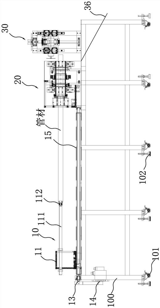
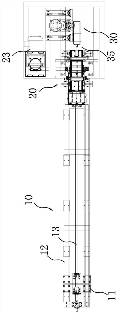
[0036] refer to figure 1 , figure 2 , image 3 , Figure 4 and Figure 5 , a pipe cutting machine, including a frame 100, the frame 100 is provided with a feeding mechanism 10, a clamping and rotating mechanism 20, and a cutting mechanism 30 in sequence, and the feeding mechanism 10 includes a traversing bracket 11, and the traversing The traversing bracket 11 can be laterally slidably erected on the frame 100 through the traversing guide rail assembly 12, and a traversing screw assembly 13 for driving its movement is connected to the traversing bracket 11, and the traversing screw assembly 13 is transmission-connected to a The traverse motor 14 drives the traverse bracket 11 to reciprocate along the traverse guide rail assembly 12; the traverse bracket 11 is erected with a pole 111, and the end of the pole 111 is rotatably provided with a rotating sleeve 112, one end of the pipe to be processed is sleeved on the rotating sleeve 112;

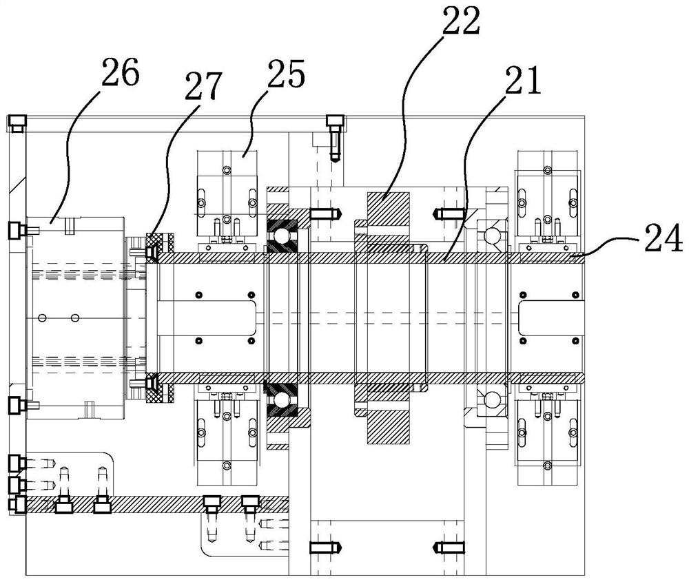
[0037]The clamping and rotating mec...


PUM


Abstract

The invention relates to the field of tube cutting equipment, in particular to a tube cutting machine which is characterized in that a feeding mechanism, a clamping rotating mechanism and a cutting mechanism are sequentially arranged on a rack, wherein the feeding mechanism comprises a transverse moving support, and a transverse moving screw assembly used for driving the transverse moving support to move is connected to the transverse moving support; the transverse moving screw rod assembly is in transmission connection with a transverse moving motor; a frame rod is erected on the transverse moving support, a rotating sleeve is rotatably arranged at the end part of the frame rod, and one end of a tube to be machined is arranged on the rotating sleeve in a sleeving mode; the clamping rotating mechanism comprises a roller erected on the rack, and a rolling assembly for driving the roller to rotate along the center and a rolling motor are arranged on the roller; two clamping block groups which can extend in a reciprocating mode in the radial direction of the roller and are used for clamping tubes are installed on the roller, each clamping block group is arranged in the circumferential face of the roller in a penetrating mode, each clamping block group is connected with a clamping block air cylinder driving the clamping block group to move, and the two clamping block groups are arranged at the two axial ends of the roller respectively.

Description

technical field [0001] The invention relates to the field of pipe cutting equipment, in particular to a pipe cutting machine, especially for the processing of carbon fiber pipes. Background technique [0002] Carbon fiber tube, also known as carbon fiber tube, also known as carbon tube, carbon fiber tube, is made of carbon fiber composite material pre-impregnated with styrene-based polyester resin and heated and cured by pultrusion (wrapping). Different molds produce various profiles, and after forming, they need to be cut and processed according to the actual installation size; and restricted by the advantages of carbon fiber tubes such as high strength, long life, corrosion resistance, light weight, and low density, in The requirements for processing equipment are very high during processing. [0003] And existing pipe cutting machine such as CN 103009418 B has shown a kind of paper tube cutting machine, comprises machine platform, speed-regulating motor, disc cutter and ...

Claims


Application Information

Patent Timeline
Patent Type & Authority Applications(China)
IPC IPC(8): B26D1/143B26D7/06B26D7/02
CPCB26D1/143B26D7/06B26D7/02
Inventor 吴金遵
Owner 晋江市恒荣碳纤制品有限公司
Why Eureka
Try Eureka