Automobile bearing seat die-casting die and die-casting process thereof
A technology for automobile bearings and die-casting molds, applied in the field of die-casting molds, can solve the problems of mold surface sticking, damage to automobile bearing seats, etc., and achieve the effect of reducing adhesion
- Summary
- Abstract
- Description
- Claims
- Application Information
AI Technical Summary
Problems solved by technology
Method used
Image

Examples
Embodiment 1
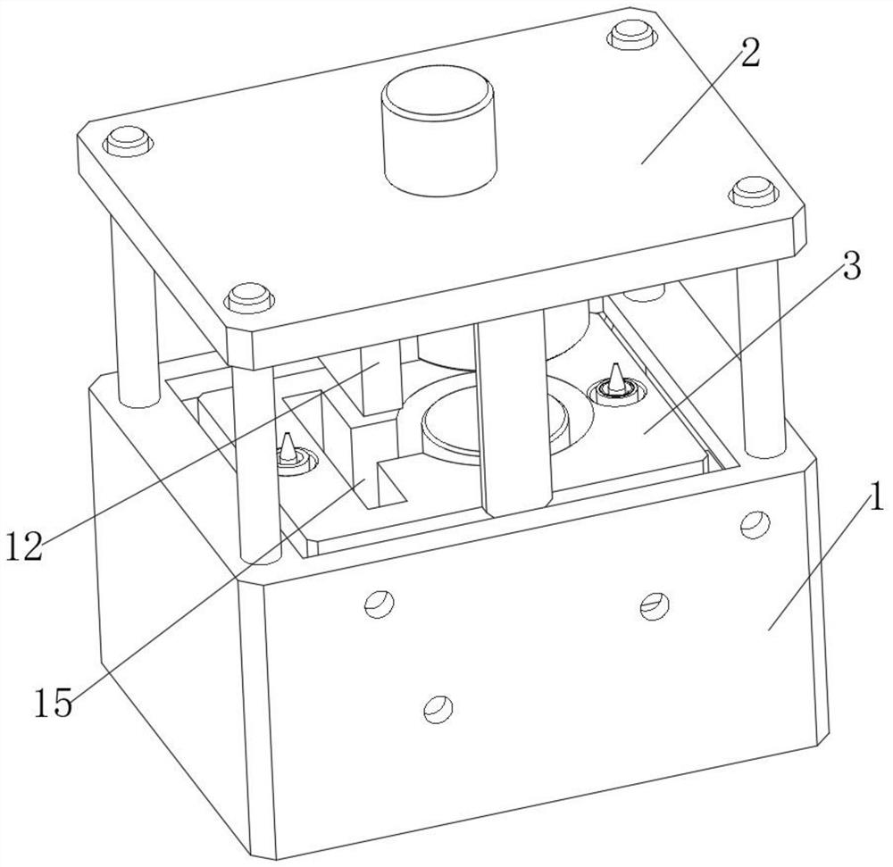
[0029] see Figure 1-4 , a die-casting mold for an automobile bearing seat, comprising a lower mold 1 and an upper mold 2 arranged on the lower mold 1, a mold core 3 is installed in the lower mold 1, a model through groove 15 is arranged in the mold core 3, and a mold through groove 15 is arranged in the lower mold 1. The first elastic piece 6 is installed, and the sealing plate 13 is installed on the first elastic piece 6, and the sealing plate 13 is used to seal the model through groove 15, and the upper mold 2 is equipped with an extrusion plate 11, and the extrusion plate 11 is used to resist the first elastic piece 6;
[0030] A limit plate 4 is installed in the lower mold 1, and the limit plate 4 is used to limit the movement of the first shrapnel 6. A support device 5 is installed on the limit plate 4. The mold core 3 and the limit plate 4 are connected through the support device 5. The support device 5 includes an L-shaped plate 51 installed on the limiting plate 4, a...
Embodiment 2
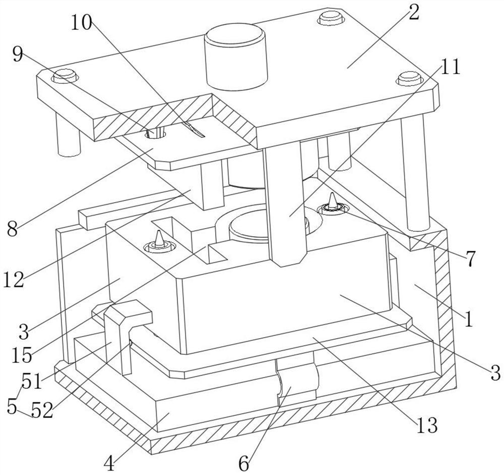
[0035] This embodiment is an improvement made on the basis of Embodiment 1, according to Figure 1-4 As shown, a second elastic piece 10 is installed on the upper mold 2 , a support plate 8 is installed on the second elastic piece 10 , and a bearing seat mold cover 12 is installed on the support plate 8 .
[0036] In this embodiment: since the bearing seat mold cover 12 at the lower end of the upper mold 2 is connected through the second elastic piece 10, when the bearing seat mold cover 12 is snapped into the inside of the mold core 3, the second elastic piece 10 will be compressed, so when the upper mold When the mold 2 is lifted, the compression force is released through the second elastic piece 10, and the second elastic piece 10 drives the bearing seat mold cover 12 to move up and down, and then assists the bearing seat mold cover 12 to be taken out from the inside of the mold core 3 to avoid the phenomenon of mold sticking.
Embodiment 3
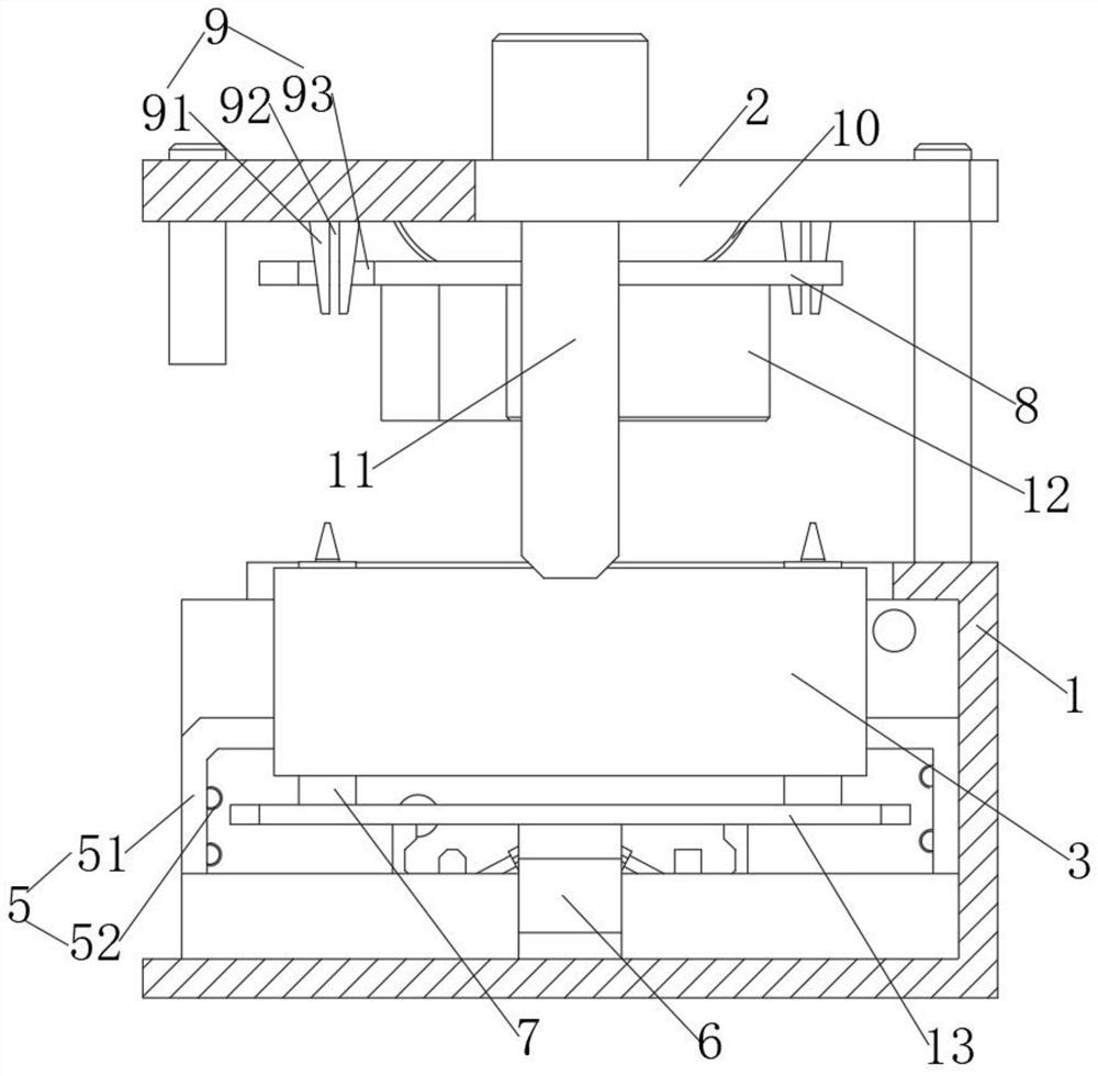
[0038] This embodiment is an improvement made on the basis of Embodiment 2, according to Figure 1-5 As shown, a limiting device 9 is also installed on the upper mold 2, and the limiting device 9 includes a tapered sleeve 91. The tapered sleeve 91 is installed on the upper mold 2, and the supporting plate 8 is provided with a through hole 93, through which the tapered sleeve 91 penetrates. The hole 93, the tapered sleeve 91 is also provided with a through groove 92, the sealing plate 13 is also equipped with a clamping device 7, the clamping device 7 is used to resist the inside of the tapered sleeve 91, the clamping device 7 includes a circular sleeve 72, The round sleeve 72 is installed on the sealing plate 13, and the mold core 3 is also provided with a round hole 71, the round sleeve 72 penetrates through the round hole 71, and the inside of the round sleeve 72 is slidably connected with a post 73, which is used to interfere with the tapered sleeve. 91, the tapered sleeve ...
PUM
 Abstract
Description
Claims
Application Information
 - Generate Ideas
- Intellectual Property
- Life Sciences
- Materials
- Tech Scout
- Unparalleled Data Quality
- Higher Quality Content
- 60% Fewer Hallucinations
Browse by: Latest US Patents, China's latest patents, Technical Efficacy Thesaurus, Application Domain, Technology Topic, Popular Technical Reports.
© 2025 PatSnap. All rights reserved.Legal|Privacy policy|Modern Slavery Act Transparency Statement|Sitemap|About US| Contact US: help@patsnap.com