
Oral cavity imbedded breathing trachea capable of continuously adsorbing saliva

A continuous, adsorption cavity technology, used in respirator, oral mirror, tracheal intubation, etc., can solve the problem of not being able to suck away in time, and achieve the effect of preventing blockage, reducing the contact area, and reducing discomfort

Inactive Publication Date: 2021-11-19
THE FIRST AFFILIATED HOSPITAL OF HENAN UNIV OF SCI & TECH
View PDF0 Cites 0 Cited by
  • Summary
  • Abstract
  • Description
  • Claims
  • Application Information

AI Technical Summary

Problems solved by technology

[0007] In order to solve the problem that the existing breathing tube cannot absorb the saliva secreted by the patient's oral cavity in time, the present invention provides a mouth-mounted breathing tube with continuous saliva absorption. The upper alveolar and the lower alveolar are fixed in the oral cavity to realize the fixation of the respiratory trachea and prevent it from being pushed out unconsciously by the patient. At the same time, it also prevents the deformation of the respiratory trachea caused by the patient's unconscious bite. A saliva adsorption mechanism is set in the fixed block of the gum to prevent the saliva The core of the adsorption mechanism is the adsorption cavity with absorbent cotton yarn and the downward extension area, so that the saliva secreted by the patient's oral cavity can be absorbed by the absorbent cotton yarn through the saliva hole, and it is only necessary to take out and replace the absorbent cotton yarn in the saliva adsorption mechanism regularly to achieve The continuous adsorption of saliva prevents saliva from accumulating in the patient's mouth and entering the airway to cause danger

Method used


Image

  • Oral cavity imbedded breathing trachea capable of continuously adsorbing saliva
  • Oral cavity imbedded breathing trachea capable of continuously adsorbing saliva
  • Oral cavity imbedded breathing trachea capable of continuously adsorbing saliva

Examples


Embodiment 1

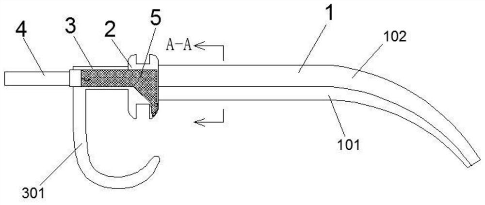
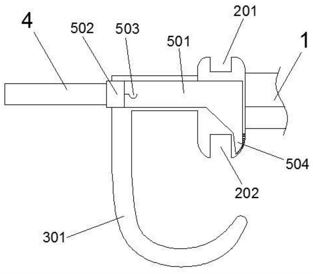
[0040] A persistent saliva-absorbing orally inserted breathing tube, such as Figure 1-3 As shown, it includes a respiratory trachea body 4 with one end connected to the ventilator and the other end extending into the oropharynx. The respiratory trachea body 4 is provided with a gum fixing block 2. The gum fixing block 2 is made of silica gel, and the gum fixing block 2 passes through it. The upper alveolar 201 and the lower alveolar 202 respectively provided on the top and the bottom are fixed on the gum bed, so as to realize the fixation of the respiratory trachea body 4; an extension body 3 extending to the outside of the oral cavity is provided on the outside of the gum bed fixing block 2, and the gum bed is fixed The outer side of the block 2 refers to the side adjacent to the lips. The respiratory trachea body 4 extends into the oropharynx through the extension body 3 and the gum fixing block 2, and a saliva adsorption mechanism 5 is arranged in the extension body 3. The...

Embodiment 2

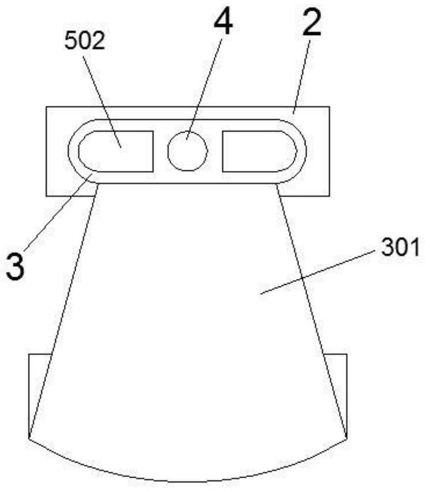
[0044] This embodiment is an improvement made on the basis of embodiment 1, its main structure is the same as that of embodiment 1, and the improvements are as follows: Figure 1-3 As shown, the outer end of the extension body 3 is provided with an auxiliary fixing clip 301 extending downward. The end of the auxiliary fixing clip 301 has a curved portion facing the side of the gum fixing block 2. Chin grip secures.

[0045] In this embodiment, the auxiliary fixing clip 301 is actually an elastic plate-shaped piece made of silica gel, whose width gradually widens from top to bottom, as shown in image 3 As shown, the curved part at the end is bent upwards so as to be stuck at the patient's chin and fixed by elastic force. A space for accommodating the chin and lips is actually formed between the auxiliary fixing clip 301 and the gum fixing block 2 .

Embodiment 3

[0047] This embodiment is another improvement made on the basis of embodiment 1, its main structure is the same as that of embodiment 1, and the improvements are as follows: figure 1 As shown, an oropharyngeal airway 1 is provided on the inner side of the fixed gum block 2, and the oropharyngeal airway 1 has a mouth end in the oral cavity and a pharyngeal end that bends and extends to the pharynx. The end of the breathing tube 4 gradually narrows toward the pharynx, or remains unchanged. The respiratory airway 4 passes through the oropharyngeal airway 1 and then extends into the oropharynx. The end of the respiratory airway 4 passes through the oropharyngeal airway 1, thereby sending oxygen into the To the oropharynx, the front end extends out of the oral cavity, and the part of the breathing trachea 4 inside the oropharyngeal airway 1 is fixedly connected with the oropharyngeal airway 1, so that the breathing trachea 4 and the oropharyngeal airway 1 act as an integrated struct...


PUM


Abstract

An oral cavity imbedded breathing trachea capable of continuously adsorbing saliva is disclosed, a gum fixing block is arranged on a breathing trachea body, the gum fixing block is fixed on a gum through an upper tooth groove and a lower tooth groove, an extension body extending to the outside of the oral cavity is arranged on the outer side of the gum fixing block, and a saliva adsorption mechanism is arranged in the extension body. The saliva adsorption mechanism comprises an adsorption cavity and a downward extending area, the downward extending area is located in the inner side wall of the lower alveolar cavity, saliva holes facing the interior of the oral cavity are distributed in the surface of the downward extending area, and the adsorption cavity and the downward extending area are filled with water-absorbing cotton yarn. The core of the saliva adsorption mechanism is the adsorption cavity with the water-absorbing cotton yarn and the downward extending area, so that saliva endocrine in the oral cavity of a patient can be adsorbed by the water-absorbing cotton yarn through the saliva hole, and the saliva can be continuously adsorbed only by regularly taking out and replacing the water-absorbing cotton yarn in the saliva adsorption mechanism; saliva is prevented from being accumulated in the oral cavity of the patient and entering the airway to cause danger.

Description

technical field [0001] The invention relates to a respiratory trachea in the field of intensive medical surgery, in particular to a breathing trachea inserted into an oral cavity for continuous saliva absorption. Background technique [0002] There are generally two types of craniotomy in critical care surgery. One is mechanical collisions that cause skull cracks, and the other is blood clots caused by alcohol or other reasons that cause blood pressure to rise and intracranial blood vessels to rupture. In these two types of craniotomies, the patient is in a coma under general anesthesia, and the base of the tongue can easily block the airway. Therefore, a ventilator and a breathing tube are needed to assist the patient to breathe. [0003] Respiratory intubation is generally used in conjunction with the oropharyngeal airway, and oxygen is introduced into the trachea through the patient's mouth. In order to prevent the patient from biting and deforming the respiratory intubat...

Claims


Application Information

Patent Timeline
IPC IPC(8): A61M16/04A61C17/10
CPCA61M16/04A61M16/0402A61M16/0497A61M16/0463A61M16/0493A61C17/10
Inventor 徐丛璇代依含
Owner THE FIRST AFFILIATED HOSPITAL OF HENAN UNIV OF SCI & TECH
Learn More