Eureka AIR delivers breakthrough ideas for toughest innovation challenges, trusted by R&D personnel around the world.

Cold storage floor construction method and cold storage floor

A construction method and floor technology, applied in refrigeration plants, industrial buildings, infrastructure projects, etc., can solve the problems of increasing the volume expansion force of water freezing, reducing the speed of cold transfer, and poor cooling effect, etc. Achieve the effect of protecting thermal performance, reducing cold heat transfer, and enhancing air tightness

Pending Publication Date: 2021-11-09
ZHEJIANG CONSTR ENG GRP CO LTD
View PDF7 Cites 1 Cited by
  • Summary
  • Abstract
  • Description
  • Claims
  • Application Information

AI Technical Summary

Problems solved by technology

However, in the above-mentioned cold storage floor construction method, although a heat insulation layer suitable for the storage temperature is installed in the cold storage floor, the cold insulation effect is actually not good, because the heat insulation layer is close to the upper and lower structural layers, so In fact, the heat insulation layer does not completely isolate the heat transfer, but only reduces the speed of cold transfer. With the use of the cold storage for years and months, as time goes by, the 0°C isotherm will gradually penetrate into the soil layer, constantly Increasing the volume expansion force generated by the freezing of water will eventually cause the floor to freeze or the foundation to heave

Method used


Image

  • Cold storage floor construction method and cold storage floor
  • Cold storage floor construction method and cold storage floor
  • Cold storage floor construction method and cold storage floor

Examples


Embodiment Construction

[0033]The following will clearly and completely describe the technical solutions in the embodiments of the present invention with reference to the accompanying drawings in the embodiments of the present invention. Obviously, the described embodiments are only some, not all, embodiments of the present invention. Based on the embodiments of the present invention, all other embodiments obtained by persons of ordinary skill in the art without making creative efforts belong to the protection scope of the present invention.

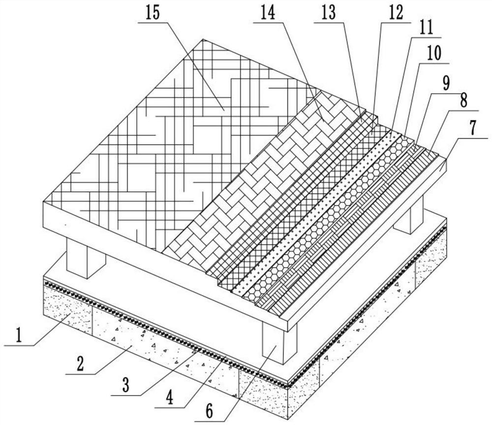
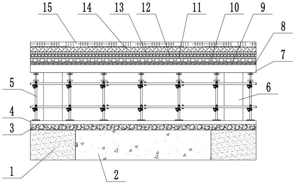
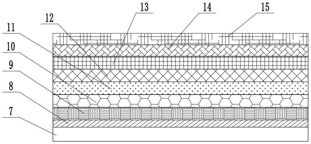
[0034] This embodiment provides a cold storage floor construction method, such as Figure 1 to Figure 3 shown, including the following steps:

[0035] S1, laying the base; pouring the foundation caps 1 on the soil layer, the foundation caps 1 are arranged in a matrix, backfilling between the foundation caps 1, and layering and compacting the backfilling soil to form the backfilling soil layer 2, and then A gravel layer 3 is laid on the top surface of the backf...


PUM

PropertyMeasurementUnit
thicknessaaaaaaaaaa
densityaaaaaaaaaa
compressive strengthaaaaaaaaaa

Abstract

The invention discloses a cold storage floor construction method, and belongs to the technical field of cold storage heat preservation. The cold storage floor construction method comprises the following steps: S1, foundation bearing platforms are poured in matrix arrangement, soil is backfilled, and a gravel layer and a foundation cushion layer are sequentially laid on a backfill soil layer and the foundation bearing platforms; S2, a bearing frame, a formwork and reinforcing steel bars are erected on the foundation cushion layer, concrete stand column formworks correspond to the foundation bearing platforms, and the formworks and the bearing frames are removed after pouring is completed; S3, a damp-proof layer is laid; and S4, a concrete floor surface layer is laid. The invention further provides a cold storage floor. The cold storage floor comprises a base layer, an overhead heat insulation layer, a damp-proof layer and the concrete floor surface layer which are sequentially arranged from bottom to top; the base layer comprises the foundation bearing platforms, the backfill soil layer, the gravel layer and the foundation cushion layer, the overhead heat insulation layer comprises concrete stand columns and a concrete top plate; the damp-proof layer is laid on the concrete top plate; and the overhead heat insulation layer can separate the floor surface layer from the base layer, cold bridge generation is reduced, cooling capacity is prevented from being transferred downwards, and cold-caused expansion of a soil layer is avoided.

Description

technical field [0001] The invention relates to the technical field of cold storage heat preservation, in particular to a construction method for a cold storage floor and the cold storage floor. Background technique [0002] In the large-span cold storage, due to the large temperature difference between the internal and external environments of the cold storage building, the water vapor penetration pressure on the cold storage floor is serious. The surface of the structure penetrates into the deep layer of the floor structure. When the storage temperature drops below 0°C, the moisture in the floor will condense into ice, and then expand. When the expansion stress is large, cracks and other problems are likely to appear on the floor. Moreover, since the temperature of the low-temperature storage is kept below 0°C all the year round, the soil layer below the floor will not be supplemented by heat, and the 0°C isotherm will gradually move to the deep layer of the soil layer, ca...

Claims


Application Information

Patent Timeline
Patent Type & Authority Applications(China)
IPC IPC(8): E02D27/14E04B5/43E04B1/66E04B1/76E04B1/80E04F15/12E04F15/14E04H5/10
CPCE02D27/14E04B5/43E04B1/665E04B1/76E04B1/80E04F15/12E04F15/14E04H5/10Y02A30/24Y02A30/244Y02B80/00
Inventor 吕俊勇楼熙捷李宗平钱良根皇甫飞飞张益周晓杰斯海金刘恒超蒋阳勇陈撑张惠黄浩贤周伟丞毛苏航王露霞王晨曦邓美珍
Owner ZHEJIANG CONSTR ENG GRP CO LTD
Why Eureka
Eureka Blog
Learn More