Flue gas waste heat recycling device for waste incineration power plant

A flue gas waste heat and waste incineration technology, applied in the direction of cleaning heat transfer devices, heat exchangers, incinerators, etc., can solve the problems of reducing heat exchange efficiency, flue gas blockage, affecting flue gas emissions, etc., to achieve efficient heat exchange, Ensure efficient heat exchange and enhance the effect of the cleaning process

Pending Publication Date: 2021-11-05
SHANGHAI TECHSPRAY ENG
View PDF0 Cites 0 Cited by
  • Summary
  • Abstract
  • Description
  • Claims
  • Application Information

AI Technical Summary

Problems solved by technology

[0002] In people's daily life, a large amount of garbage will inevitably be produced. If these garbage are not treated effectively, it will greatly affect people's living environment. "The best way to dispose of domestic waste has attracted great attention and attention from the state. During the process of waste incineration, most of the smoke generated is discharged from the incinerator through the exhaust pipe. The smoke from burning waste contains a lot of heat and has not been fully utilized.
[0003] Some waste incineration plants use the heat around the exhaust pipe by installing a water storage tank outside the exhaust pipe, but the water storage tank that absorbs heat is mostly located on the outer wall of the exhaust pipe, which does not directly contact the flue gas for heat exchange. The efficiency is low. Putting the heat-absorbing water storage tank in the exhaust pipe will cause the smoke to be blocked. The burning of garbage will produce a large amount of black smoke. The black smoke contains a lot of particulate impurities, which will settle on the outer wall of the water storage tank. , which further affects the emission of flue gas and reduces the heat exchange efficiency. In view of the above situation, a device for recovering waste heat from waste incineration power plants is needed

Method used


Image

  • Flue gas waste heat recycling device for waste incineration power plant
  • Flue gas waste heat recycling device for waste incineration power plant
  • Flue gas waste heat recycling device for waste incineration power plant

Examples


Embodiment Construction

[0030] The present invention will be further described below in conjunction with the accompanying drawings and embodiments.

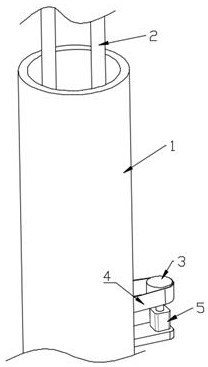
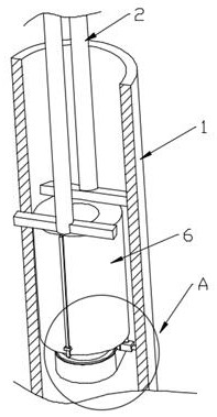
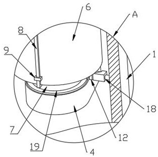
[0031] refer to Figure 1-7 , a device for recovering and utilizing flue gas waste heat in a waste incineration power plant, comprising an exhaust pipe 1 for discharging flue gas, the interior of the exhaust pipe 1 is fixedly connected with a heat-absorbing block 6, and the heat-absorbing block 6 is provided with a channel in the vertical direction, and the air-absorbing The heat block 6 is provided with a liquid storage chamber for loading heat-conducting liquid. Two water pipes 2 are fixedly connected to the upper end of the heat-absorbing block 6. Both water pipes 2 communicate with the liquid storage chamber, and the two water pipes 2 communicate with an external water tank. A water pipe 2 is provided with a water pump, which can replace the liquid in the heat-absorbing block 6 to realize heat exchange. There is a gap between the heat-absorbing bloc...


PUM


Abstract

The invention provides a flue gas waste heat recycling device for a waste incineration power plant. The flue gas waste heat recycling device for the waste incineration power plant comprises an exhaust pipe used for exhausting flue gas, a heat absorption block is fixedly connected to the interior of the exhaust pipe, a channel is formed in the heat absorption block in the vertical direction, a liquid storage cavity used for containing heat conduction liquid is formed in the heat absorption block, two water pipes are fixedly connected to the upper end of the heat absorption block, the two water pipes communicate with a cavity, a circular ring is rotationally connected to the lower end of the heat absorption block, a dust removal rod is fixedly connected to the circular ring, a hollow wheel is fixedly connected to the lower end of the circular ring, and a driving mechanism used for driving the dust removal rod to rotate through the circular ring is arranged on the hollow wheel. According to the flue gas waste heat recycling device for the waste incineration power plant, waste heat in the flue gas can be stably and efficiently recycled, and part of impurity particles in the flue gas can be removed.

Description

technical field [0001] The invention relates to the technical field of waste gas utilization, in particular to a device for recovering and utilizing waste heat from flue gas in a waste incineration power plant. Background technique [0002] In people's daily life, a large amount of garbage will inevitably be produced. If the garbage is not treated effectively, it will greatly affect people's living environment. "The best way to dispose of domestic waste has attracted great attention and attention from the state. During the process of waste incineration, most of the smoke generated is discharged from the incinerator through the exhaust pipe. The smoke from burning waste contains a lot of heat and has not been fully utilized. [0003] Some waste incineration plants use the heat around the exhaust pipe by installing a water storage tank outside the exhaust pipe, but the water storage tank that absorbs heat is mostly located on the outer wall of the exhaust pipe, which does not ...

Claims


Application Information

Patent Timeline
IPC IPC(8): F23G5/46F28D21/00F28G13/00
CPCF23G5/46F28D21/0003F28G13/00
Inventor 赵清华付永强朱晔斐邹贞郭伟夏懿
Owner SHANGHAI TECHSPRAY ENG
Why Eureka
Try Eureka