Hot air conveying device of non-woven fabric production equipment
A technology for production equipment and conveying devices, which is applied in the field of hot air conveying devices, can solve the problems of poor impurity cleaning effect, low degree of automation, and poor filtering effect, and achieve the effect of improving the filtering effect and service life, and improving the cleaning degree
- Summary
- Abstract
- Description
- Claims
- Application Information
AI Technical Summary
Problems solved by technology
Method used
Image
Examples
Embodiment 1
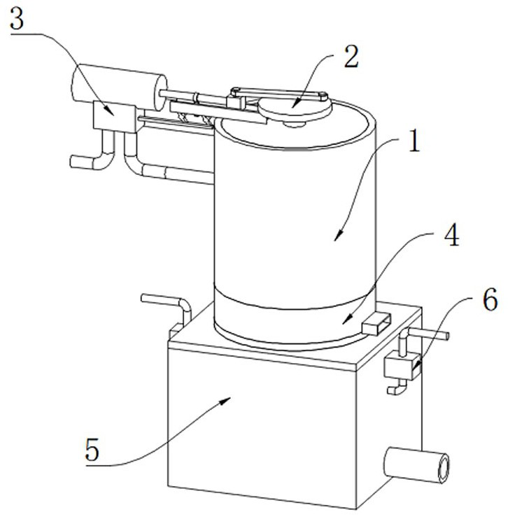
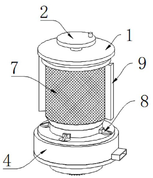
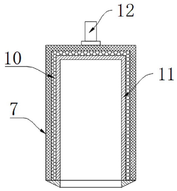
[0032] see figure 2 As shown, a hot air conveying device for non-woven fabric production equipment includes a purification box 1, the top middle of the purification box 1 is movably connected with a rotating shaft 12, and the rotating shaft 12 extends to the inner cavity of the purification box 1 and its bottom is fixed. Connect with filter screen 7, the inwall of filter screen 7 is provided with nano-silver ion layer 10, the inwall of nano-silver ion layer 10 is provided with activated carbon layer 11, and the inwall of purification box body 1 is all fixedly connected with the left and right sides of filter screen 7 The brush plate 9, the top of the rotating shaft 12 is fixedly connected with the turntable 2, and the left side wall of the purification box 1 is fixedly equipped with a steam drive mechanism 3, and its design purpose is: when the push rod 123 moves around periodically, it will push the sliding The block 24 slides left and right in the inner cavity of the chute ...
Embodiment 2
[0034] see Figure 5 As shown, it is basically the same as Embodiment 1. Furthermore, the steam driving mechanism 3 includes a mounting plate 18, the right side wall of the mounting plate 18 is fixedly connected with the left side wall of the purification box 1, and the front of the mounting plate 18 is fixedly installed. Piston cylinder 19 is arranged, and the inner cavity of piston cylinder 19 is slidably connected with piston plate one 35, and the right side wall of piston plate one 35 is fixedly connected with push rod one 23, and the right side wall of push rod one 23 is fixedly connected with slide block 24, The top of the slider 24 is movably connected with a movable plate 25, and the end of the movable plate 25 away from the slider 24 is movably connected with the eccentric position of the turntable 2. The top of the purification box 1 is fixedly connected with a chute 26, and the slider 24 is in the chute 26. The inner chamber of the piston barrel is slidingly connect...
Embodiment 3
[0040] see Figure 8 As shown, it is basically the same as the second embodiment, furthermore, the liquid filling mechanism 6 includes a liquid storage housing 41, the inner cavity of the liquid storage housing 41 is provided with an air bag 42, and the inner cavity of the air bag 42 is provided with a spring 43 transversely, The end of the push rod three 39 away from the gear frame 38 extends to the inner cavity of the liquid storage housing 41 and its end is fixedly connected with the second piston plate 44, the second piston plate 44 is slidingly connected with the inner wall of the liquid storage housing 41, and the top of the air bag 42 and the bottom are provided with a one-way valve connected from top to bottom, the upper one-way valve is externally connected to the disinfectant tank, and the lower one-way valve extends away from the end of the liquid adding mechanism 6 to the inner cavity of the disinfection box 5, and its The end is fixedly connected with a water spra...
PUM
 Abstract
Description
Claims
Application Information
 - R&D
- Intellectual Property
- Life Sciences
- Materials
- Tech Scout
- Unparalleled Data Quality
- Higher Quality Content
- 60% Fewer Hallucinations
Browse by: Latest US Patents, China's latest patents, Technical Efficacy Thesaurus, Application Domain, Technology Topic, Popular Technical Reports.
© 2025 PatSnap. All rights reserved.Legal|Privacy policy|Modern Slavery Act Transparency Statement|Sitemap|About US| Contact US: help@patsnap.com


