Low-delay semi-dynamic trigger based on tunneling field effect transistor hybrid integration

A technology of semi-dynamic trigger and tunneling field effect, which is applied in the direction of pulse generation, electrical components, and electric pulse generation. It can solve the problems of increasing circuit switching activity and increasing dynamic power consumption, so as to improve frequency performance and reduce dynamic switching. The effect of power consumption

Pending Publication Date: 2021-11-02
SOUTHEAST UNIV
View PDF6 Cites 0 Cited by
  • Summary
  • Abstract
  • Description
  • Claims
  • Application Information

AI Technical Summary

Problems solved by technology

[0005] However, if the TFET circuit is fully used, due to the influence of the TFET Miller effect, it will increase unnecessary switching activities in the circuit and increase dynamic power consumption. Therefore, it is necessary to partially re...

Method used


Image

  • Low-delay semi-dynamic trigger based on tunneling field effect transistor hybrid integration
  • Low-delay semi-dynamic trigger based on tunneling field effect transistor hybrid integration
  • Low-delay semi-dynamic trigger based on tunneling field effect transistor hybrid integration

Examples


Embodiment

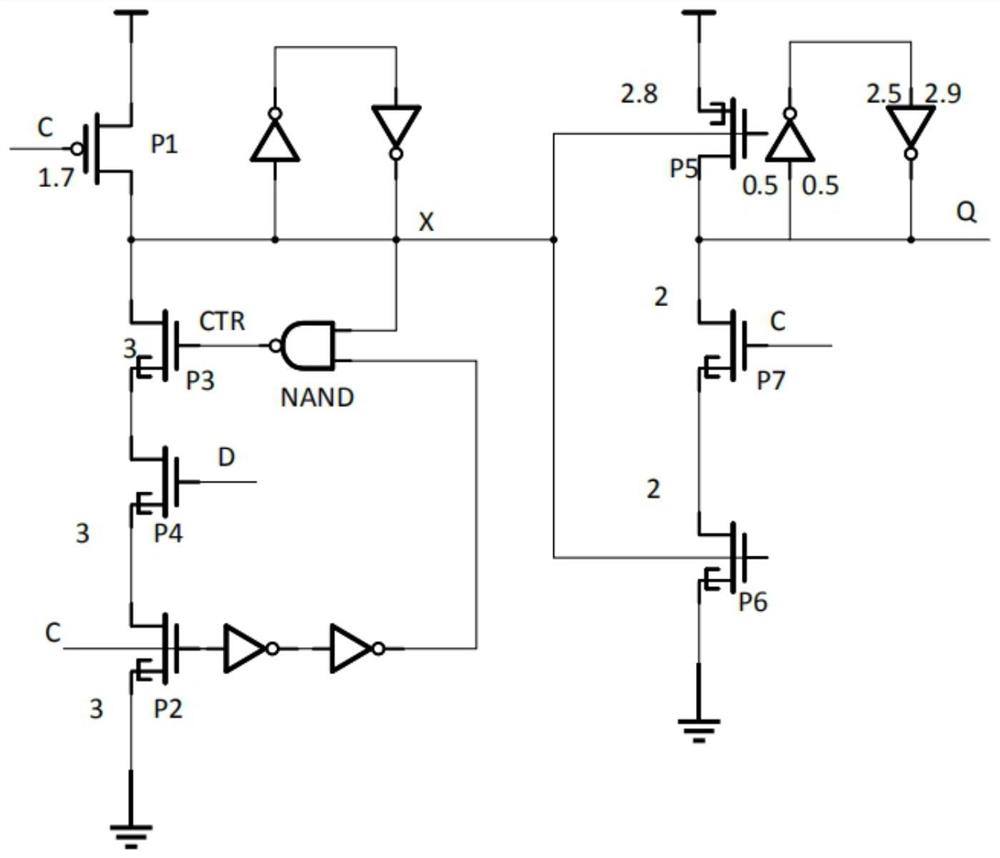
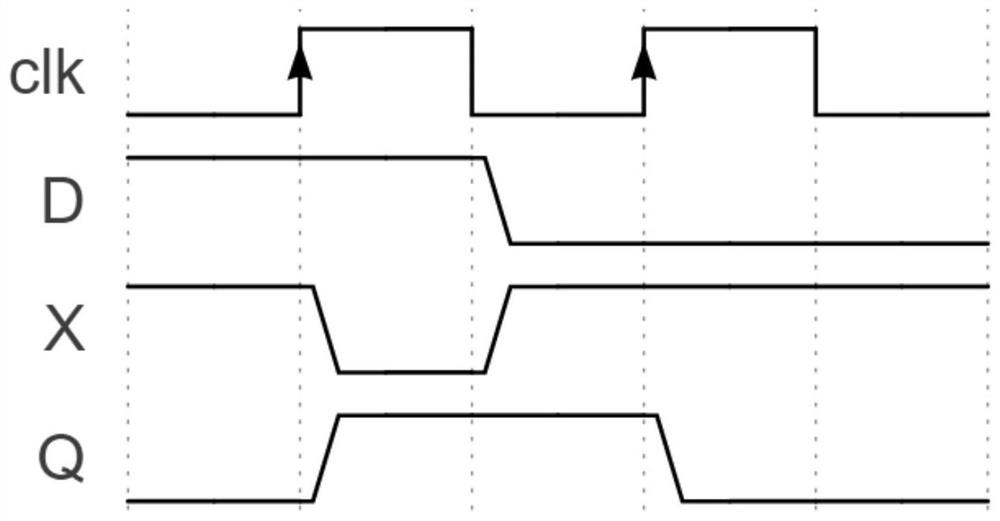
[0025] The present invention is based on a low-delay semi-dynamic flip-flop integrated with tunneling field effect transistors. The flip-flop uses TFETs to replace MOSFETs and CMOS logic gates in the critical path of the circuit. and a static backend for latching and outputting data. The dynamic front-end circuit consists of a pull-up circuit, a pull-down circuit and a latch. The pull-up circuit is a P-type MOSFET, and the pull-down circuit uses three N-type TFET transistors, two A TFET inverter and a TFET NAND gate replace the original MOSFET and CMOS logic gate; the static output circuit uses a pull-up P-type TFET and two pull-down N-type TFET transistors to replace the original MOSFET, followed by a CMOS latch. in:

[0026] The four transistors in the front-end dynamic circuit are the first pull-up transistor P1, the first pull-down transistor P2, the discharge transistor P3 and the data input transistor P4, the first pull-up transistor P1 is a P-MOSFET, and its gate is con...


PUM


Abstract

The invention discloses a low-delay semi-dynamic flip-flop based on tunneling field effect transistor hybrid integration. The flip-flop comprises a dynamic front-end circuit and a static rear-end circuit, the dynamic front-end circuit is composed of a pull-up circuit, a pull-down circuit and a latch, the pull-up circuit is a P-type metal insulated gate transistor. The pull-down circuit comprises three N-type TFET transistors, two TFET phase inverters and a TFET NAND gate; the static output circuit uses a pull-up P-type TFET and two pull-down N-type TFETs and then is connected with a CMOS latch. Under the working voltages of 0.55 V, 0.5 V, 0.45 V and 0.4 V, the clock output (C2q) delay and retention time are remarkably reduced compared with a full MOSFET circuit, the clock output (C2q) delay and retention time are most remarkable under the voltage of 0.4 V and are reduced by 90% and 147% respectively, and the power delay product is reduced compared with a full TFET circuit.

Description

technical field [0001] The invention relates to the field of integrated circuits, in particular to a semi-dynamic flip-flop circuit structure based on tunneling field effect transistor (TFET) hybrid integration. Background technique [0002] As a basic component of a sequential circuit, a flip-flop is one of the essential components in electronic products. A basic flip-flop consists of two latches connected end to end. In order to optimize the performance of the flip-flop, the flip-flop has various structures, such as figure 1 The semi-dynamic flip-flop structure (Semi-Dynamic Flip-Flop) composed of P-type metal insulated gate transistors (MOSFETs) is shown, which consists of two parts: a dynamic front end and a static back end. This structure has low delay, high stability, There are many advantages such as small clock load. [0003] In recent years, with the rapid development of embedded devices and wearable devices, the size of electronic products required by the industr...

Claims


Application Information

Patent Timeline
IPC IPC(8): H03K3/356
CPCH03K3/356104
Inventor 马逸茗洪小锋蔡浩
Owner SOUTHEAST UNIV
Why Eureka
Try Eureka