A boiler water cooling recovery device
A technology for cooling and recycling device and boiler water, which is applied in separation methods, greenhouse gas reduction, filtration and separation, etc., and can solve the problems of filter clogging, poor filtering effect, and difficulty in cleaning the filter.
- Summary
- Abstract
- Description
- Claims
- Application Information
AI Technical Summary
Problems solved by technology
Method used
Image

Examples
Embodiment 1
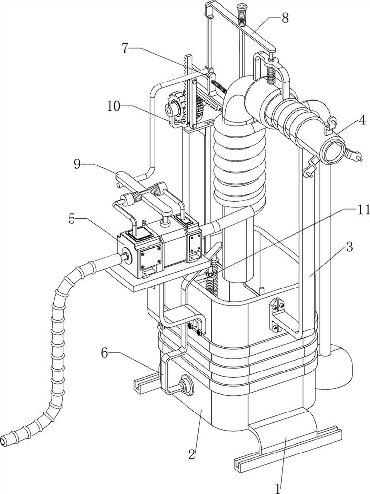
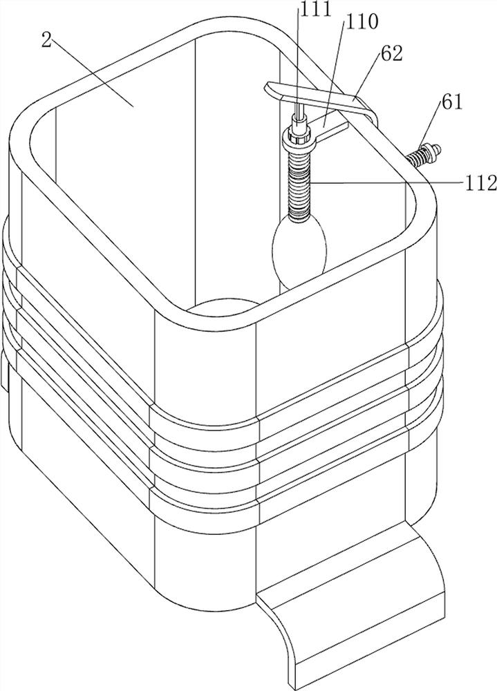
[0065] A boiler water cooling recovery device, such as figure 1 and figure 2 As shown, it includes a support plate 1, a water storage tank 2, a support block 3, a drain pipe 4, a cooling mechanism 5 and a drainage mechanism 6. The left and right sides of the bottom of the water storage tank 2 are provided with a support plate 1, and the upper part of the right side of the water storage tank 2 is provided with a support plate 1. There is a support block 3, the upper part of the support block 3 is provided with a drain pipe 4, the other end of the drain pipe 4 is located above the water storage tank 2, the upper part of the front side of the water storage tank 2 is provided with a cooling mechanism 5, and the upper part of the front side of the water storage tank 2 is provided with a drainage mechanism 6, The drainage mechanism 6 is located on the left side of the cooling mechanism 5 .
[0066] The cooling mechanism 5 includes a support seat 50, a water pump 51 and a water del...
Embodiment 2
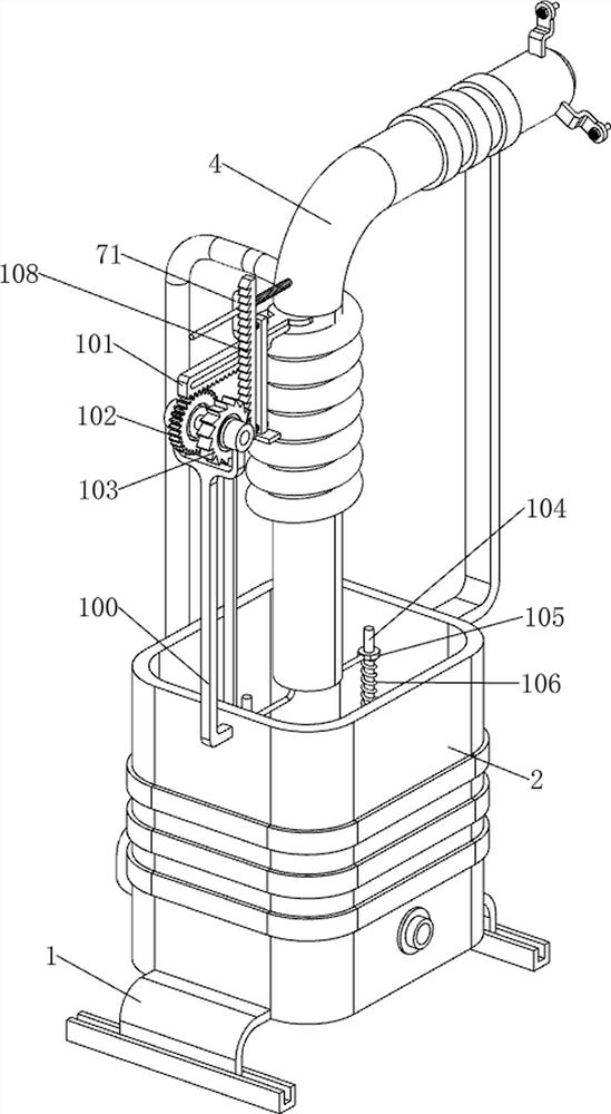
[0070] On the basis of Example 1, as figure 1 , image 3 and Figure 4 As shown, a water blocking mechanism 7 is also included. The water blocking mechanism 7 includes a second guide rod 70, a water blocking plate 71 and a second spring 72. The upper left side of the drain pipe 4 is provided with a second guide rod 70. The second guide rod The middle of the rod 70 is slidably provided with a water blocking plate 71. The water blocking plate 71 blocks the upper left side of the drain pipe 4, and a second spring 72 is wound around the right side of the second guide rod 70. The two ends of the second spring 72 are respectively connected to the water blocking plate. 71 and drain pipe 4 are connected.
[0071] It also includes an induction mechanism 8. The induction mechanism 8 includes a third guide rod 80, a clamping rod 81, a connecting plate 82, a third spring 83, a first guide plate 84, an air bag 85 and a fourth spring 86. The top of the drain pipe 4 is left on the left sid...
Embodiment 3
[0074] On the basis of Example 2, as figure 1 , Figure 5 , Image 6 , Figure 7 and Figure 8 As shown, a trigger mechanism 9 is also included. The trigger mechanism 9 includes a first bearing seat 90, a rotating plate 91, a torsion spring 92 and a trigger rod 93. The top and front sides of the water pump 51 are provided with a first bearing seat 90. A rotating plate 91 is rotatably provided between the upper left side of the bearing seat 90, the rotating plate 91 cooperates with the water pump 51, a torsion spring 92 is arranged between the rotating plate 91 and the two first bearing seats 90, and the lower part of the front side of the clamping rod 81 A trigger rod 93 is provided, and the trigger rod 93 cooperates with the turning plate 91 .
[0075] When the clamping rod 81 moves upward, it drives the trigger rod 93 to move upward, the trigger rod 93 drives the rotating plate 91 to rotate, the torsion spring 92 is deformed, and the rotating plate 91 touches the switch ...
PUM
 Abstract
Description
Claims
Application Information
 - R&D
- Intellectual Property
- Life Sciences
- Materials
- Tech Scout
- Unparalleled Data Quality
- Higher Quality Content
- 60% Fewer Hallucinations
Browse by: Latest US Patents, China's latest patents, Technical Efficacy Thesaurus, Application Domain, Technology Topic, Popular Technical Reports.
© 2025 PatSnap. All rights reserved.Legal|Privacy policy|Modern Slavery Act Transparency Statement|Sitemap|About US| Contact US: help@patsnap.com