


Quick Research
Generate reliable direction feasibility study reports for your R&D in just a few steps.

Technical Q&A
Discover and master advanced knowledge NOW. Basics, ideas, possibilities, all at once.

Find Solutions
As an expert in R&D theories, this can generate solutions to your technical problems instantly.

Evaluate Feasibility
Analyze your overall solution with one click, know your potential R&D risks in advance.

Monitor Landscape
Get weekly tech updates, stay abreast of the latest tech innovations and key insights.
PVC particle filtering device for optical fibers
A technology of particle filtration and optical fiber, which is applied in the fields of filtration, solid separation, chemical instruments and methods, etc. It can solve the problems of low work efficiency and low precision of PVC particles, and achieve the effect of improving work efficiency and avoiding stuck
- Summary
- Abstract
- Description
- Claims
- Application Information
AI Technical Summary
Problems solved by technology
Method used
Image

Examples
Embodiment 1
[0075] A PVC particle filter device for optical fiber, such as figure 1 As shown, it includes a bottom plate 1, a first support column 2, a servo motor 3, a drum filter mechanism 4, and a shaking mechanism 5. The first support column 2 is symmetrically arranged on the right side of the top of the bottom plate 1, and the left side of the top of the bottom plate 1 is connected to the first A drum filter mechanism 4 is arranged between the tops of the support columns 2 , a servo motor 3 is arranged on a certain part of the drum filter mechanism 4 , and a shaking mechanism 5 is arranged on the drum filter mechanism 4 .
[0076] When people need to filter the PVC particles, all the PVC particles are first poured into a certain part of the drum filter mechanism 4, then the servo motor 3 is started, and the output shaft of the servo motor 3 drives the drum filter mechanism 4 to run, and the drum filter mechanism 4 drives The shaking mechanism 5 operates, and the drum filter mechanism...
Embodiment 2
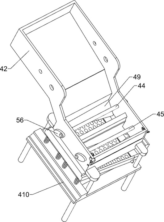
[0078] On the basis of Example 1, such as figure 2 , image 3 , Figure 4 and Figure 5 As shown, the drum filter mechanism 4 includes a second support column 41, a blanking basket 42, a first pulley set 43, a first rotating shaft 44, a second rotating shaft 45, a small hole drum 46, a large hole drum 47, a first baffle plate 48. The first limiting plate 49 and the workbench 410, the left side of the top of the bottom plate 1 is provided with a workbench 410, and the front and rear sides of the top of the workbench 410 are provided with two second support columns 41, and the top of the second support column 41 is connected to the first A blanking basket 42 is arranged between the tops of a supporting column 2, and the left part of the front side of the top of the blanking basket 42 is connected with the bottom of the servo motor 3, and the left part of the blanking basket 42 is rotatably provided with a first rotating shaft 44, and the left side of the blanking basket 42 is...
Embodiment 3
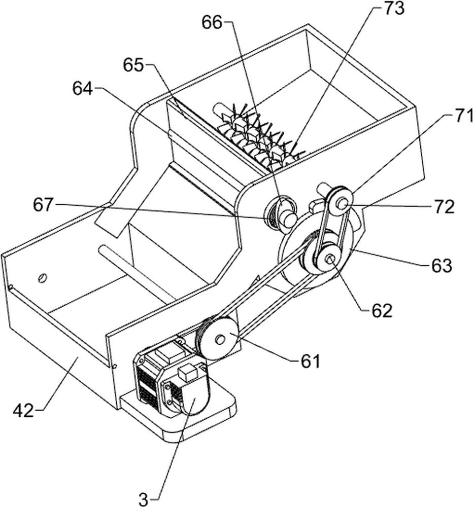
[0085] On the basis of Example 2, such as Figure 5 , Figure 6 and Figure 7 As shown, a stirring mechanism 7 is also included, and the stirring mechanism 7 includes a third pulley set 71, a sixth rotating shaft 72 and a blade 73, and the right part of the blanking basket 42 is rotated to be provided with a sixth rotating shaft 72, and the sixth rotating shaft 72 is located at the first On the right side of the fifth rotating shaft 64 , a third pulley set 71 is provided between the front of the sixth rotating shaft 72 and the front of the fourth rotating shaft 62 , and a blade 73 is arranged on the sixth rotating shaft 72 .
[0086] When the fourth rotating shaft 62 rotates, the third pulley set 71 drives the sixth rotating shaft 72 and the blade 73 to rotate, and the blade 73 stirs the PVC particles in the blanking basket 42 to prevent the PVC particles from being blocked in the second baffle plate 65 .
[0087] Also includes a blocking mechanism 8, the blocking mechanism...
PUM
 Abstract
Description
Claims
Application Information
 - R&D Engineer
- R&D Manager
- IP Professional
- Industry Leading Data Capabilities
- Powerful AI technology
- Patent DNA Extraction
Browse by: Latest US Patents, China's latest patents, Technical Efficacy Thesaurus, Application Domain, Technology Topic, Popular Technical Reports.
© 2024 PatSnap. All rights reserved.Legal|Privacy policy|Modern Slavery Act Transparency Statement|Sitemap|About US| Contact US: help@patsnap.com