


Quick Research
Generate reliable direction feasibility study reports for your R&D in just a few steps.

Technical Q&A
Discover and master advanced knowledge NOW. Basics, ideas, possibilities, all at once.

Find Solutions
As an expert in R&D theories, this can generate solutions to your technical problems instantly.

Evaluate Feasibility
Analyze your overall solution with one click, know your potential R&D risks in advance.

Monitor Landscape
Get weekly tech updates, stay abreast of the latest tech innovations and key insights.
Boiler water cooling recovery device
A cooling recovery device, boiler water technology, applied in the separation method, greenhouse gas reduction, filtration and separation, etc., can solve the problems of poor filtering effect, filter blockage, difficult to clean the filter, etc.
- Summary
- Abstract
- Description
- Claims
- Application Information
AI Technical Summary
Problems solved by technology
Method used
Image

Examples
Embodiment 1
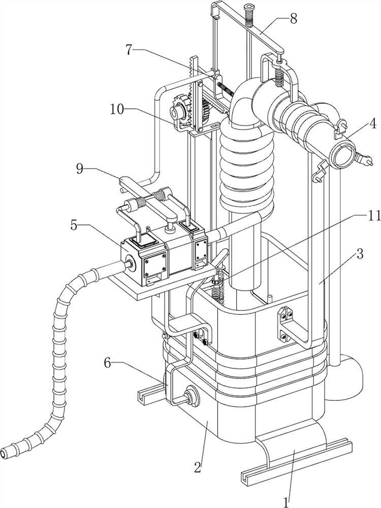
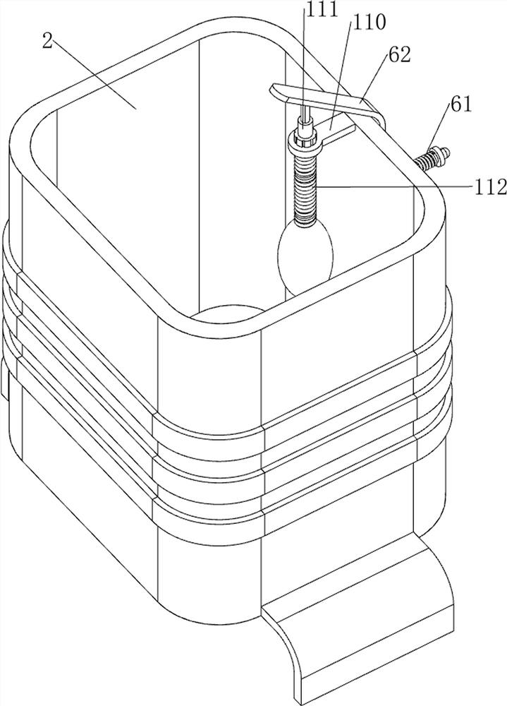
[0065] A boiler water cooling recovery device, such as figure 1 and figure 2 As shown, it includes a support plate 1, a water storage tank 2, a support block 3, a drain pipe 4, a cooling mechanism 5 and a drainage mechanism 6. The left and right sides of the bottom of the water storage tank 2 are provided with a support plate 1, and the upper part of the right side of the water storage tank 2 is provided with a support plate 1. There is a support block 3, the upper part of the support block 3 is provided with a drain pipe 4, the other end of the drain pipe 4 is located above the water storage tank 2, the upper part of the front side of the water storage tank 2 is provided with a cooling mechanism 5, and the upper part of the front side of the water storage tank 2 is provided with a drainage mechanism 6, The drainage mechanism 6 is located on the left side of the cooling mechanism 5 .
[0066] The cooling mechanism 5 includes a support base 50, a water pump 51 and a water del...
Embodiment 2
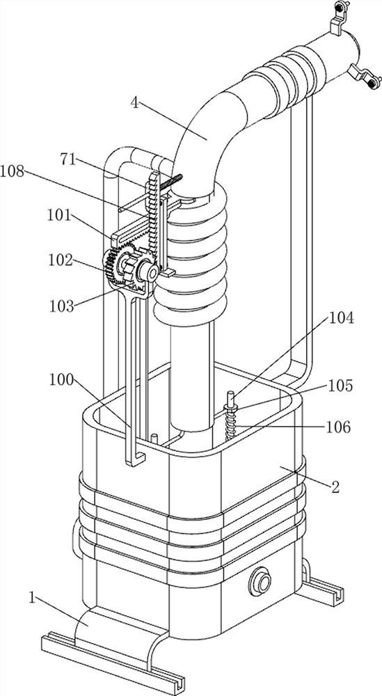
[0070] On the basis of Example 1, such as figure 1 , image 3 and Figure 4 As shown, a water blocking mechanism 7 is also included. The water blocking mechanism 7 includes a second guide rod 70, a water blocking plate 71 and a second spring 72. The upper left side of the drain pipe 4 is provided with a second guide rod 70. The second guide The middle part of the rod 70 is slidingly provided with a water blocking plate 71, the water blocking plate 71 blocks the inner upper left side of the drain pipe 4, and a second spring 72 is wound on the right side of the second guide rod 70, and the two ends of the second spring 72 are connected with the water blocking plate respectively. 71 is connected with drainpipe 4.
[0071] Induction mechanism 8 is also included, and induction mechanism 8 includes a third guide rod 80, a clamping rod 81, a connecting plate 82, a third spring 83, a first guide plate 84, an air bag 85 and a fourth spring 86. Side is provided with the 3rd guide bar...
Embodiment 3
[0074] On the basis of Example 2, such as figure 1 , Figure 5 , Figure 6 , Figure 7 and Figure 8 As shown, a trigger mechanism 9 is also included. The trigger mechanism 9 includes a first bearing seat 90, a rotating plate 91, a torsion spring 92 and a trigger lever 93. The front and rear sides of the top of the water pump 51 are provided with a first bearing seat 90. A rotating plate 91 is arranged between the left side of the upper part of the bearing block 90, and the rotating plate 91 cooperates with the water pump 51. A torsion spring 92 is arranged between the rotating plate 91 and the two first bearing blocks 90, and the lower part of the front side of the clamping rod 81 A trigger lever 93 is provided, and the trigger lever 93 cooperates with the rotating plate 91 .
[0075] When the clamping rod 81 moves upwards, it drives the trigger lever 93 to move upward, the trigger lever 93 drives the rotating plate 91 to rotate, the torsion spring 92 deforms, and the rot...
PUM
 Abstract
Description
Claims
Application Information
 - R&D Engineer
- R&D Manager
- IP Professional
- Industry Leading Data Capabilities
- Powerful AI technology
- Patent DNA Extraction
Browse by: Latest US Patents, China's latest patents, Technical Efficacy Thesaurus, Application Domain, Technology Topic, Popular Technical Reports.
© 2024 PatSnap. All rights reserved.Legal|Privacy policy|Modern Slavery Act Transparency Statement|Sitemap|About US| Contact US: help@patsnap.com