Lead screw mounting structure for grinding machine

A technology of installation structure and screw, which is applied to the parts of grinding machine tools, devices for fixing grinding wheels, grinding/polishing equipment, etc. Reduce problems such as reducing the impact on accuracy and life, improve rigidity and stability, and reduce the amount of overhang

Pending Publication Date: 2021-10-26
上海欧博自控技术装备有限公司
View PDF1 Cites 0 Cited by
  • Summary
  • Abstract
  • Description
  • Claims
  • Application Information

AI Technical Summary

Problems solved by technology

[0006] 1. The weight of the grinding head and grinding wheel frame of the machine tool is relatively large, and the gravity directly acts on the screw rod. If the traditional angular contact bearing is used, in order to ensure the service life, the size of the angular contact bearing must be increased. The entire grinding head and The overhang of the grinding wheel frame increases, and the rigidity and stability of the machine tool decrease;
[0007] 2. If the traditional stretching structure is used, in order to completely offset the gravity of the grinding head and the grinding wheel frame and the thermal elongation of the screw rod during processing, the tensile force is much larger than that of the traditional machine tool, and the deformation of the screw rod is large, which will affect the wire rod. The pre-tightening force of the rod nut affects the service life of the screw rod; if the pre-tightening force is reduced, the stretching of the screw rod will not be sufficient. The failure of the end support affects the feed speed and feed accuracy;
[0008] 3. If the traditional self-compensating structure is adopted, the movement of the butterfly spring is not flexible, and the inner hole of the butterfly spring is easy to cause damage and wear to the surface of the screw, which affects the service life of the screw; the stiffness curve of the butterfly spring is a nonlinear curve , the tensile force of the screw rod is difficult to adjust, and the tensile force changes greatly with the change of the compression amount, while the vertical axis of the CNC vertical grinding machine is used for high-speed and heavy-duty applications, and the tensile force is required to change after the screw rod is deformed Small, so the butterfly spring is not suitable for vertical grinders, and the nut that compresses the butterfly spring is not easy to tighten when installed vertically, and the installation is inconvenient

Method used


Image

  • Lead screw mounting structure for grinding machine
  • Lead screw mounting structure for grinding machine
  • Lead screw mounting structure for grinding machine

Examples


Embodiment

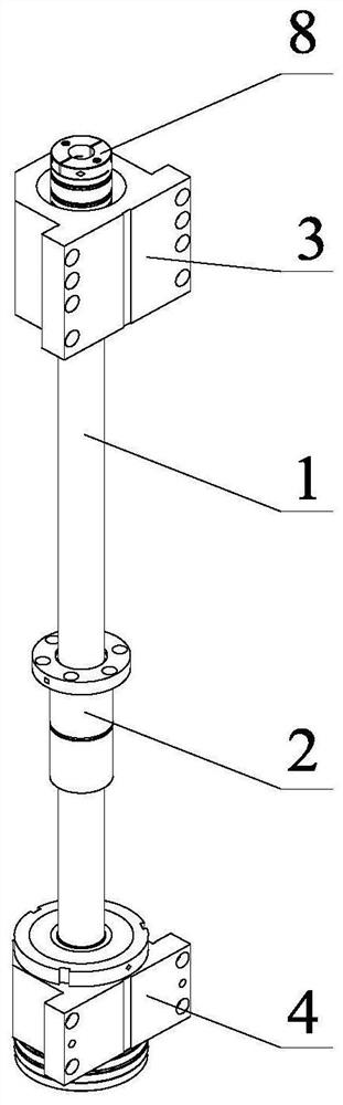
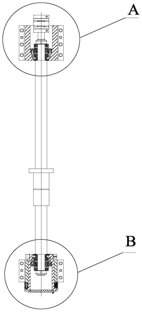
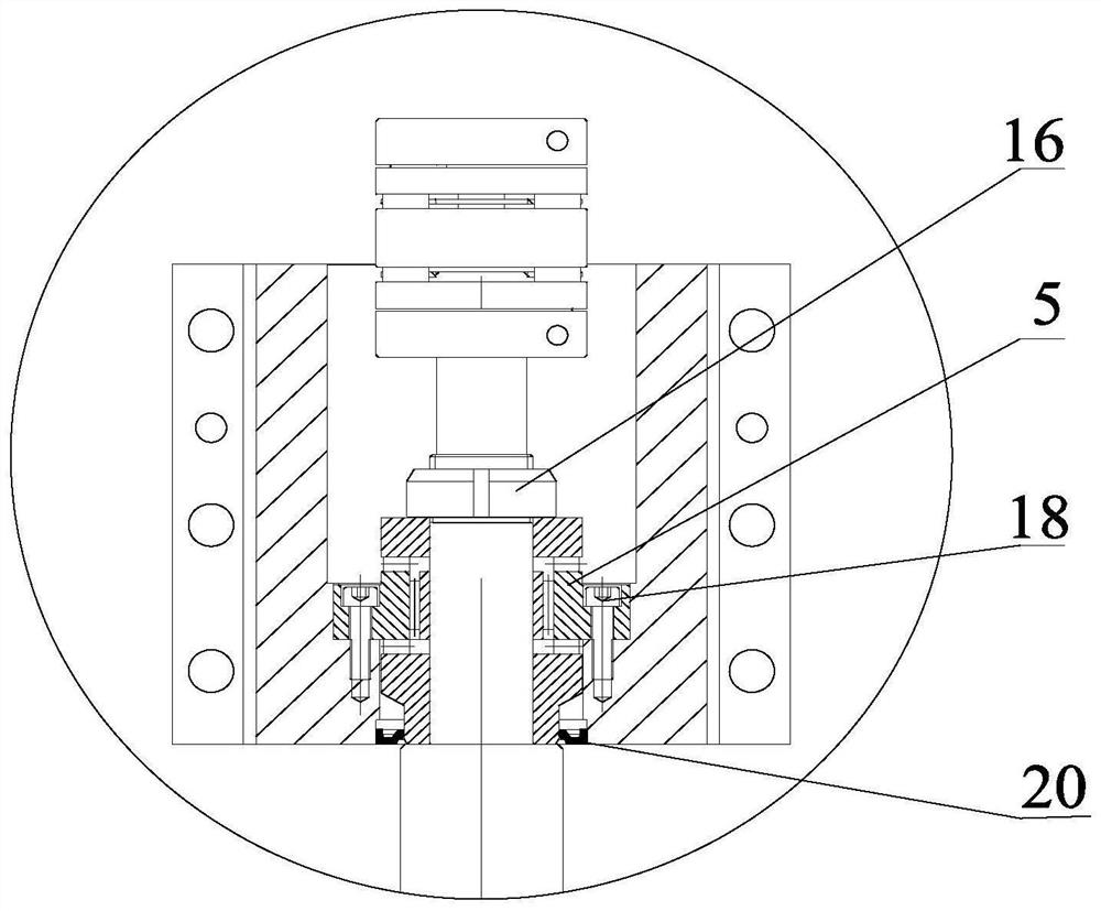
[0047] refer to figure 1 As shown, this embodiment discloses a screw mounting structure for a grinder, including a screw 1, a support assembly for supporting the rotation of the screw 1, a drive motor for driving the rotation of the screw 1, and a Screw nut 2; the support assembly includes a first support seat 3 and a second support seat 4, the first support seat 3 is provided with a first roller bearing 5, and the second support seat 4 is provided with a flange type sliding sleeve 7 , There is a second roller bearing 6 inside the flange type sliding sleeve 7 .

[0048] Wherein, one end of the screw rod 1 is installed in the first support seat 3 through the first roller bearing 5, and the other end is installed in the second support seat 4 through the second roller bearing 6; the screw rod 1 is located in the first support seat 3 One end of the shaft coupling 8 is installed, and the screw mandrel 1 is connected with the driving motor (not shown in the figure) through the shaf...

Embodiment 2

[0064] This embodiment discloses a numerically controlled vertical grinding machine, which includes a workbench system and an abrasive belt grinding head. The workbench system includes a workbench and an X-axis screw rod. The workbench is installed on the X-axis rail at the top of the frame base through a slider. , the worktable is connected to the X-axis nut seat on the X-axis screw rod, and the X-axis deceleration motor is installed at the rear end of the X-axis screw rod; the abrasive belt grinding head includes a polishing frame plate, a machine head seat, an abrasive belt mechanism and a Z-direction feed mechanism , the polished shelf includes two side shelves and a top shelf, the two side shelves are installed on both sides of the frame base, the top shelf is installed on the top of the side shelf, and the inner side of the side shelf is equipped with a Z To the feed mechanism, wherein the Z-direction feed mechanism in this embodiment is the screw installation mechanism d...


PUM


Abstract

The invention discloses a lead screw mounting structure for a grinding machine. The lead screw mounting structure comprises a supporting assembly which is used for supporting a lead screw to rotate. The supporting assembly comprises a first supporting base and a second supporting base. A first roller bearing is arranged in the first supporting base, a flange type sliding sleeve is arranged in the second supporting base in a sliding mode, and a second roller bearing is arranged in the flange type sliding sleeve. The flange type sliding sleeve is connected with the second supporting base through a forcing screw and a stretching compensation piece. Compared with an existing lead screw mounting structure, the lead screw mounting structure for the grinding machine has the advantages that the structural size is small, the outer overhanging amount of a whole grinding head and the outer overhanging amount of a grinding wheel frame can be reduced, and therefore the rigidity and the stability of a numerical control vertical grinding machine system are improved. Meanwhile, when a lead screw is installed on a machine tool, installation is easy and convenient, save labor and is rapid, before installation is conducted, the pre-stretching force of the lead screw is set through the forcing screw and the stretching compensation piece, and therefore the stretching amount of the lead screw can be quantitatively controlled so as to adapt to the pre-stretching amount of the lead screw in different working environments.

Description

technical field [0001] The invention relates to the technical field of screw rod installation structures, in particular to a screw rod installation structure for a grinding machine. Background technique [0002] CNC machine tools are the main precision cutting tools in modern high-precision manufacturing, and the structure of the machine tool affects the accuracy of the machine tool. The transmission accuracy of the screw plays an important role in the accuracy of the machine tool and is directly related to the machining accuracy of the machine tool. Therefore, the transmission structure of the machine tool, the accuracy of the bearing, and the thermal deformation of the screw directly affect the machining accuracy of the machine tool. Therefore, the screw and The installation structure and method of the bearing are very important. [0003] In order to achieve high feed speed and feed accuracy, most of the existing machine tool screw installation structures adopt fixed inst...

Claims


Application Information

Patent Timeline
Patent Type & Authority Applications(China)
IPC IPC(8): B24B41/04B24B45/00B24B41/00
CPCB24B41/04B24B45/003B24B41/007
Inventor 王家富孙涛吴琼
Owner 上海欧博自控技术装备有限公司
Why Eureka
Try Eureka