Pneumatic plate shearing machine

A technology of pneumatic shears and plate shears, which is applied in the direction of shearing machine equipment, shearing devices, metal processing equipment, etc., and can solve the problems of difficult high-precision product processing, precision difficult to ensure mutual cooperation, large geometric deviation, etc. problem, to achieve the effect of convenient and sensitive operation and use, small vibration, precise coordination and controllable

Inactive Publication Date: 2013-10-16
新昇电气有限公司
View PDF7 Cites 4 Cited by
  • Summary
  • Abstract
  • Description
  • Claims
  • Application Information

AI Technical Summary

Problems solved by technology

[0002] In industrial production, the shearing of steel plates is processed by shearing machines, while the traditional shearing machines use electric motors as the power source to allow the shearing knives to reciprocate up and down. During the continuous reciprocating motion, In particular, the beams of the existing equipment and the uprights on both sides are integrally formed by cast iron, and it is difficult to ensure the precision of the entire body to cooperate with each other. Adapt to the processing and use of high-precision products

Method used


Image

  • Pneumatic plate shearing machine

Examples


Embodiment Construction

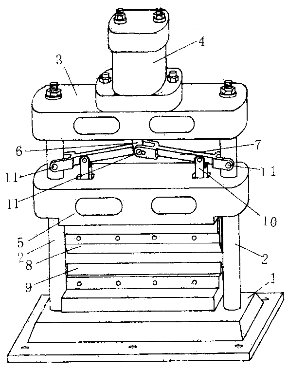
[0011] figure 1 As shown: a column 2 is arranged on both sides of a fixed base 1, and a cylinder 4 is installed on the top of the two columns 2 through a fixed beam 3, and the piston rod 6 in the cylinder 4 passes through the columns 2 on both sides. The movable beam 5 of the suit is equipped with an upper cutter 8, and the upper cutter 8 and the fixed lower cutter 9 of the base 1 constitute a corresponding shearing structure. The lower end of the piston rod 6 in the cylinder 4 is connected with the remote arm 7 fixed on the columns 2 on both sides through the pin shaft 11, and a connecting rod 10 is respectively fixed on the movable beam 5 at the remote arm 7 both sides. The remote arm 7 is connected and fixed with the uprights 2 on both sides by a pin shaft 11 .

[0012] When specifically implementing this technical solution, a guide inner sleeve should be added between the movable beam 5 and the column 2. The material of the guide inner sleeve should be the same steel as t...


PUM


Abstract

The invention provides a pneumatic plate shearing machine. The plate shearing machine is characterized in that two upright posts are respectively arranged on two sides of a base which can be fixed; a cylinder is mounted at the tops of the upright posts through a fixed beam; an upper shearing knife is mounted on a piston rod in the cylinder through a movable beam which is mounted on the upright posts on two sides of the piston rod in a sleeving manner; the mounted upper shearing knife and a lower shearing knife fixed on the base form an anastomotic corresponding shearing structure. When the pneumatic plate shearing machine is used, the movable beam can quickly and powerfully do up-and-down reciprocating movement through the cylinder, so that the upper shearing knife and the lower shearing knife are driven to form an excellent shearing knife; the movable beam is directly mounted on the upright posts in a sleeving manner to form an up-and-down corresponding relation with the lower shearing knife, so that the shearing precision is high; besides, the cylinder is adopted as a shearing power source, so that the shearing is fast; the operation is sensitive. The pneumatic plate shearing machine is scientific and simple in integral structure and particularly suitable for serving as a small-sized shearing machine for processing precise steel plates.

Description

technical field [0001] The invention relates to a shearing machine, in particular to a pneumatic shearing machine. Background technique [0002] In industrial production, the shearing of steel plates is processed by shearing machines, while the traditional shearing machines use electric motors as the power source to allow the shearing knives to reciprocate up and down. During the continuous reciprocating motion, In particular, the beams of the existing equipment and the uprights on both sides are integrally formed by cast iron, and it is difficult to ensure the precision of the entire body to cooperate with each other. It is suitable for the processing and use of high-precision products. Contents of the invention [0003] The object of the present invention is to provide a pneumatic shearing machine, which has the characteristics of scientific and simple structure, sensitive operation and high precision of processed products. [0004] The invention includes the base ...

Claims


Application Information

Patent Timeline
Patent Type & Authority Applications(China)
IPC IPC(8): B23D15/08B23D15/14
Inventor 何建华
Owner 新昇电气有限公司
Why Eureka
Try Eureka