Electric fan with liquid bearing

A fan and rotating shaft technology, applied in the field of fans using fluid bearings, can solve the problems of high manufacturing cost and complicated fan structure, and achieve the effect of low manufacturing cost and simple structure

Inactive Publication Date: 2006-06-14
HONG FU JIN PRECISION IND (SHENZHEN) CO LTD +1
View PDF0 Cites 3 Cited by
  • Summary
  • Abstract
  • Description
  • Claims
  • Application Information

AI Technical Summary

Problems solved by technology

In order to ensure that the bearing has good ventilation and pressure building effects, these two parts must have high manufacturing and assembly precision, which makes the fan structure more complicated and the manufacturing cost high

Method used


Image

  • Electric fan with liquid bearing
  • Electric fan with liquid bearing
  • Electric fan with liquid bearing

Examples


Embodiment Construction

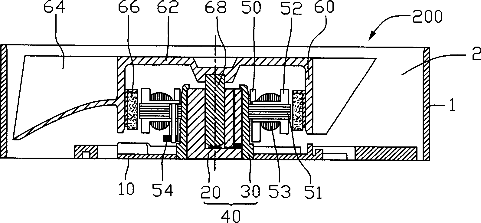
[0017] see figure 2 The fan 200 of the present invention includes a fan frame 1 with a cavity 2 in the middle, and a motor located in the cavity 2 . Wherein, the fan frame 1 is made of plastic material and includes a base 10 supporting other parts of the fan 200 . The motor includes a support 40 , a stator assembly 50 disposed around the support 40 , and a rotor assembly 60 rotatably supported on the support 40 . The supporting member 40 is disposed in the middle of the base 10 , and includes a shaft tube 30 disposed on the base 10 and a shaft sleeve 20 inside the shaft tube 30 .

[0018] The stator assembly 50 is disposed around the outer wall of the shaft tube 30 and includes a plurality of silicon steel sheets 51 , a pair of insulating frames 52 located at the upper and lower ends of the silicon steel sheets 51 , and a coil 53 wound on the insulating frames 52 . The coil 53 and the silicon steel sheet 51 are separated by an insulating frame 52 . The coil 53 is electrica...


PUM


Abstract

A fan using a fluid bearing comprises a fan frame, a support member disposed in the middle of the fan frame, a stator assembly and a rotor assembly disposed in the periphery of the support member. The support member being a single structure includes an axle hole. The rotor assembly comprises a rotation shaft held in the axle hole and a magnet opposite to the stator assembly. The lubricating fluid held between the support member and the rotation shaft.

Description

【Technical field】 [0001] The invention relates to a fan, in particular to a fan using a fluid bearing. 【Background technique】 [0002] At this stage, fluid bearing devices have been increasingly applied to fan motors to reduce the wear of the main shaft, prolong the service life of the motor, and reduce the noise during rotation. [0003] like figure 1 Shown is a fluid bearing device of a conventional fan. The motor of the fan includes a sleeve 81, a main shaft 80 located in the sleeve 81 and having a certain gap with the sleeve 81, and lubricating fluid is stored in the gap to provide Medium of fluid pressure. When there is a certain relative speed between the main shaft 80 and the sleeve 81, the lubricating fluid around the main shaft 80 generates pressure to continuously push the main shaft 80, so that the main shaft 80 does not contact the sleeve 81 in the radial direction during the rotation, and avoids wear and noise generation. In order to obtain a better pressure...

Claims


Application Information

Patent Timeline
Patent Type & Authority Applications(China)
IPC IPC(8): F04D29/04F04D25/08
Inventor 黄晋兴洪健隆施文章白先声
Owner HONG FU JIN PRECISION IND (SHENZHEN) CO LTD
Why Eureka
Try Eureka