
Optical soliton optical gyroscope system

An optical gyroscope and optical soliton technology, applied in the field of optics, can solve problems affecting gyroscope performance indicators, thermal non-reciprocity noise, uneven temperature field distribution, etc., to improve output accuracy, low bit error rate, and reduce related optical noise effect

Active Publication Date: 2021-10-22
SHAANXI RAILWAY INST
View PDF5 Cites 0 Cited by
  • Summary
  • Abstract
  • Description
  • Claims
  • Application Information

AI Technical Summary

Problems solved by technology

The first generation of laser gyroscope, although the laser gyroscope has been successfully developed and applied in practice, it is necessary to use a mechanical shaking device to overcome the locking phenomenon of the system, and it requires ultra-high-precision optical processing and very strict gas sealing, and the assembly process is more complicated.
The second-generation interferometric optical gyroscope, because the greater the length and radius of the optical fiber, the greater the Sagnac effect of the gyroscope system. Therefore, if the interferometric optical gyroscope needs to improve the detection accuracy, the length of the optical fiber needs to be increased. Currently, 2-3km long As a sensitive medium, the optical fiber coil realizes angular velocity detection, which not only increases the cost of the gyroscope, but also causes uneven distribution of the temperature field due to the increase in the length of the optical fiber, which causes thermal non-reciprocity noise in the system, thereby affecting the performance index of the gyroscope.
[0006] In order to break through the shortcomings of the optical gyro waveguide cavity, such as large loss in the transmission process, complex noise causes, and difficulty in integration, the invention replaces and improves the traditional communication laser light source system

Method used


Image

  • Optical soliton optical gyroscope system

Examples


Embodiment Construction

[0021] A kind of optical soliton optical gyro system of the present invention is further described below in conjunction with accompanying drawing and specific embodiment:

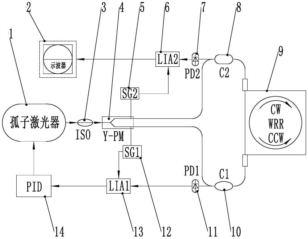
[0022] figure 1 It is a schematic diagram of a connection wire frame of an optical soliton optical gyroscope system of the present invention. In the figure, the optical soliton optical gyro system includes a soliton laser 1, and the soliton laser 1 is connected with an optical isolator 3, and the optical isolator 3 is connected with a modulation beam splitter 4, and the modulation beam splitter 4 is connected in parallel with a first optical The circulator 10 and the second optical circulator 8, the two optical circulators 8 and 10 are merged and connected to the waveguide resonator 9, the first optical circulator 10 is also connected with the first photodetector 11, and the second optical circulator 8 is also connected with the second photodetector 7, and the first photodetector 11 is connected with the f...


PUM


Abstract

The invention discloses an optical soliton optical gyroscope system which comprises a soliton laser, the soliton laser is connected with an optical isolator, the optical isolator is connected with a modulation beam splitter, the modulation beam splitter is connected with two optical circulators in parallel, and the two optical circulators are combined and connected to a waveguide resonant cavity. The two optical circulators are respectively connected with photoelectric detectors, the two photoelectric detectors are respectively connected with phase-locked amplifiers, one phase-locked amplifier is connected with an integral proportional differential frequency-locked circuit system, the integral proportional differential frequency-locked circuit system is connected to the soliton laser, and the other phase-locked amplifier is connected with a monitoring oscilloscope. And the two phase-locked amplifiers are respectively connected to the modulation beam splitter through the function signal generator. The optical soliton optical gyroscope system has very obvious advantages in the aspects of improving the accuracy, the stability and the integration of the gyroscope and reducing the manufacturing cost.

Description

technical field [0001] The invention belongs to the field of optical technology, and in particular relates to an optical soliton optical gyroscope system. Background technique [0002] Since the 1970s, optoelectronic science has developed rapidly, especially with the invention of lasers and the advent of low-transmission-loss optical fibers as milestones. Optical fiber technology is subversive in the fields of optical communication, optical sensing, and optical information processing. It has greatly changed people's production and life, such as it is widely used in medicine, industry, military and other fields. [0003] As a device for measuring the rotation of the carrier relative to the inertial space, the gyroscope is the core component of the inertial navigation system and has been widely used in the navigation of aerospace vehicles, aircraft, missiles, ships and vehicles, robot control and other fields. The gyro performance index directly determines the performance of ...

Claims


Application Information

Patent Timeline
IPC IPC(8): G01C19/72
CPCG01C19/72G01C19/721
Inventor 安盼龙赵瑞娟王语园惠亮亮姜留涛郭一航
Owner SHAANXI RAILWAY INST
Learn More