
A control valve, a control oil circuit and a variable compression ratio engine

A technology for controlling oil circuit and control valve, which is applied in the direction of engine control, machine/engine, mechanical equipment, etc., can solve the problems of high processing and production cost, increased oil circuit, complex structure, etc., achieves compact overall structure and reduces layout space the effect of the request

Active Publication Date: 2022-06-21
GUANGZHOU AUTOMOBILE GROUP CO LTD
View PDF0 Cites 0 Cited by
  • Summary
  • Abstract
  • Description
  • Claims
  • Application Information

AI Technical Summary

Problems solved by technology

At present, there are mainly two kinds of connecting rod devices that realize variable compression ratio. One is to use a mechanical valve as the switching control valve of the compression ratio, which requires a motor and a mechanical rod to trigger the switching control valve. The connecting rod of the actuator has many oil circuits. The layout space requirements are high; the other is to use the spring valve as the switching control valve of the compression ratio, but in order for the oil body in the high and low hydraulic chamber of the connecting rod to return to the oil supply chamber of the crankshaft connecting rod, it is necessary to add multiple control valves. Valves also lead to an increase in the number of oil circuits arranged, and the requirements for the layout space are also high. The control valves and corresponding control oil circuits used in the above two methods all have the disadvantages of complex structure, high requirements for space layout, and high processing and production costs.

Method used


Image

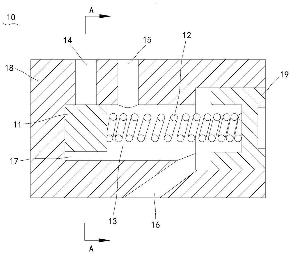
  • A control valve, a control oil circuit and a variable compression ratio engine
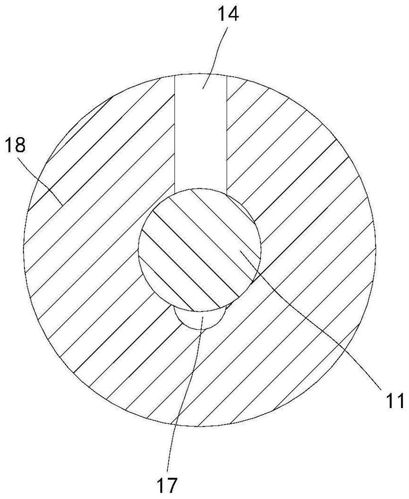
  • A control valve, a control oil circuit and a variable compression ratio engine
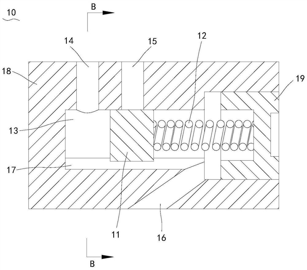
  • A control valve, a control oil circuit and a variable compression ratio engine

Examples


Embodiment Construction

[0031] The specific embodiments of the present invention will be described in further detail below with reference to the accompanying drawings and embodiments. The following examples are intended to illustrate the present invention, but not to limit the scope of the present invention.

[0032] In the description of the present invention, it should be noted that the terms "upper", "lower", "front", "rear", "left", "right", "vertical", "horizontal", "top", The orientation or positional relationship indicated by "bottom", "inside", "outside", etc. is based on the orientation or positional relationship shown in the accompanying drawings, and is only for the convenience of describing the present invention and simplifying the description, rather than indicating or implying the indicated device or Elements must have a particular orientation, be constructed, and operate in a particular orientation and are therefore not to be construed as limitations of the invention.

[0033] In the ...


PUM


Abstract

The invention relates to the technical field of engines, and discloses a control valve, a control oil circuit and a variable compression ratio engine including the control valve. The control valve includes a valve body, a valve core and an elastic member. The piece is connected to the first end of the valve chamber. The valve body is provided with a first inlet, a second inlet and a return port respectively connected with the valve chamber. The return groove communicates with the return port, and the control valve is applied to variable compression Compared with the control oil circuit of the engine, the return channel can be switched in a single control valve to realize the automatic oil filling and oil drain function of the two hydraulic chambers of the connecting rod control oil circuit, without the need to arrange too many oil circuits and reduce the layout space. It is required that the length of the connecting rod is switched by controlling the oil passage to realize the change of the engine compression ratio, so that the overall structure of the engine is compacted.

Description

technical field [0001] The present invention relates to the technical field of engines, in particular to a control valve, a control oil circuit and a variable compression ratio engine including the same. Background technique [0002] Variable compression ratio technology is a revolutionary technology in engine development. The use of high compression ratio at low load in the engine can improve the thermal efficiency of the engine and reduce fuel consumption. The use of low compression ratio at high load can improve the power and torque of the engine and meet the power requirements. . At present, there are mainly two kinds of connecting rod devices for realizing variable compression ratio. One is a switching control valve that uses a mechanical valve as the compression ratio, which requires a motor and a mechanical rod to trigger the switching control valve. The actuator has many connecting rod control oil circuits. The layout space requirements are high; the other is to use...

Claims


Application Information

Patent Timeline
Patent Type & Authority Patents(China)
IPC IPC(8): F02D15/02F02B75/04
CPCF02D15/02F02B75/045
Inventor 罗海鹏吴琪占文锋易敬华
Owner GUANGZHOU AUTOMOBILE GROUP CO LTD
Learn More