
A hand-held fastening and grinding robot for edge banding

A technology of robots and edge banding, which is applied in the direction of grinding racks, parts of grinding machine tools, and machine tools suitable for grinding the edge of workpieces, etc. It can solve the problems of affecting construction speed, tediousness, and complicated pressure application process, and achieves Guaranteed pressure effect and improved work efficiency

Active Publication Date: 2022-05-17
SINOWOLF PLASTIC DEKOR
View PDF0 Cites 0 Cited by
  • Summary
  • Abstract
  • Description
  • Claims
  • Application Information

AI Technical Summary

Problems solved by technology

[0003] At present, most of the furniture in interior decoration is customized, especially the integrated wardrobe and integrated desk bed, which need to be made on site by carpentry; edge banding is often used in production, and the edge banding is pasted on the board by applying glue on the edge banding After the edge banding is pasted, pressure needs to be applied, and the process of applying pressure is more complicated and cumbersome; if tape is required to fasten the edge banding and board, it is necessary to apply pressure with hands or wooden strips for a certain period of time; the operation requires a certain amount of time. Experience can guarantee the quality; in addition, traditionally, only after the glue is dry can it be polished to affect the construction speed

Method used


Image

  • A hand-held fastening and grinding robot for edge banding
  • A hand-held fastening and grinding robot for edge banding
  • A hand-held fastening and grinding robot for edge banding

Examples


Embodiment Construction

[0043] The specific implementation manners of the present invention will be further described in detail below in conjunction with the accompanying drawings and embodiments. The following examples or drawings are used to illustrate the present invention, but not to limit the scope of the present invention.

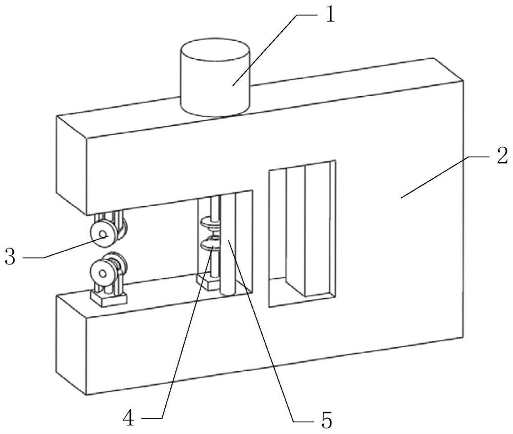
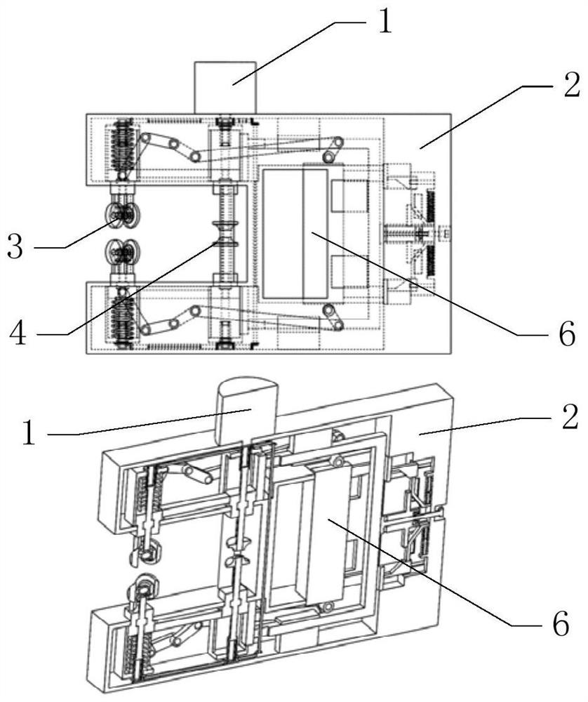
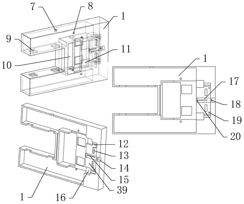
[0044] Such as figure 1 , 2 As shown, it includes a motor 1, a housing 2, a fastening mechanism 3, a grinding mechanism 4, and a trigger block 6, among which image 3 As shown, the front end of the housing 2 has a U-shaped groove, and the rear end of the housing 2 has a square groove 10; as figure 1 , 9 As shown, the trigger pressure block 6 is slidably installed in the square groove 10; the motor 1 is fixedly installed on the upper side of the housing 2, as figure 2 , 4 As shown, the two fastening mechanisms 3 are symmetrically installed at the front end of the U-shaped groove of the housing 2, and the two grinding mechanisms 4 are symmetrically installed at the rear...


PUM


Abstract

The invention belongs to the technical field of edge banding fastening and grinding, and in particular relates to a hand-held fastening and grinding robot for edge banding, which includes a motor, a housing, a fastening mechanism, a grinding mechanism, and a trigger block. In the invention, the edge banding The unique design of pressure exerts pressure on the hand-held device itself, and does not require artificial pressure, which ensures the effect of pressure exertion. On the other hand, in the process of applying pressure while the glue is not dry, grinding is carried out simultaneously under the action of the pressure roller, and the equipment designed by the invention can complete the two steps simultaneously, which improves the working efficiency. The present invention designs a limit mechanism, and the function of the limit mechanism is to ensure that the two second mounting sliders of the two grinding wheels will not be installed in the first guide sliding shell corresponding to the frictional resistance during the grinding process. Sliding affects the grinding of the edge of the edge strip by the grinding wheel.

Description

[0001] Technical field [0002] The invention belongs to the technical field of edge banding fastening and grinding, and in particular relates to a hand-held fastening and grinding robot for edge banding. Background technique [0003] At present, most of the furniture in interior decoration is customized, especially the integrated wardrobe and integrated desk bed. After the edge banding strip is pasted, pressure needs to be applied, and the process of applying pressure is more complicated and cumbersome; if tape is required to fasten the edge banding strip and board, it is necessary to apply pressure with hands or wooden strips for a certain period of time; the operation requires a certain amount of time. Experience can guarantee quality; in addition, traditionally, only after the glue is dry can it be polished to affect the construction speed. [0004] Aiming at the working characteristics of woodworking on-site production, the present invention designs a hand-held fastening...

Claims


Application Information

Patent Timeline
Patent Type & Authority Patents(China)
IPC IPC(8): B24B9/18B24B23/02B24B41/02B24B41/04B24B41/06B24B47/12B24B47/22
CPCB24B23/02B24B9/18B24B41/04B24B47/22B24B41/02B24B41/06B24B47/12
Inventor 朱振伟刘培义陈彦勤
Owner SINOWOLF PLASTIC DEKOR
Learn More