Milling method for double-sided frame part

A technology for milling and parts, applied in the field of milling of double-sided frame parts, can solve the problems of high cost, cumbersome use, time-consuming and labor-intensive, etc., and achieve the effect of stable processing and increased manufacturing cost.

Active Publication Date: 2021-09-28
CHENGDU AIRCRAFT INDUSTRY GROUP
View PDF12 Cites 1 Cited by
  • Summary
  • Abstract
  • Description
  • Claims
  • Application Information

AI Technical Summary

Problems solved by technology

[0005] (1) The cost of special fixtures is too high, and its value is even several times or even ten times that of the parts themselves
[0006] (2) The installation and use of special fixtures are cumbersome, and some fixtures also need to lay sealing strips for the vacuum adsorption area, which is time-consuming and laborious
If things go on like this, more and more special fixtures will accumulate, resulting in a large occupation of factory space
[0008] The problems of high cost, cumbersome use, and space occupation caused by traditional process methods have seriously affected the production efficiency of structural parts, and cannot meet the huge demand of my country's rapidly developing military and civilian aircraft market. Therefore, it is important to design and develop better process methods. significance

Method used


Image

  • Milling method for double-sided frame part
  • Milling method for double-sided frame part
  • Milling method for double-sided frame part

Examples


Embodiment 1

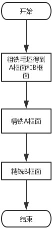
[0042] A milling method for double-sided frame parts, such as figure 1 shown, including the following steps:

[0043] S1: A frame surface and B frame surface are respectively obtained on the upper and lower sides of the rough milling blank, and the process allowance reserved for the B frame surface is greater than the process allowance reserved for the A frame surface;

[0044] S2: Stress-free clamping, fine milling of the A frame surface, machining to the theoretical size, no process allowance;

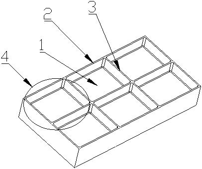
[0045] S3: Finish milling of the B frame surface, locate the rib 3 and the top surface of the edge 2 of the A frame surface after finishing milling in step S2, and when processing the web 1, use axial milling without delamination and use the B frame surface The center of the sash 4 is the starting point for milling the web 1 from the inside out. Such as Figure 9 As shown, the axial milling without delamination refers to the processing method of sequentially processing the web 1 h...

Embodiment 2

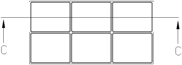
[0049] This embodiment is optimized on the basis of embodiment 1, such as Figure 5 and Figure 6 As shown, in the step S1, the process margin h1 reserved for the A frame surface is 1-5 mm, and the process margin h2 reserved for the B frame surface is 5-10 mm. In the finishing milling process, the A frame surface is firstly fine-milled, and the B frame surface is secondly fine-milled. When finishing milling A frame surface, due to the larger process allowance reserved for B frame surface, the conventional tooling method can be used for fine milling A frame surface; the small process allowance reserved for A frame surface is easier to finish milling ; On the other hand, when finishing milling the B frame surface, the larger process margin on the B frame surface can ensure the strength of the web 1 and prevent the vibration of the web 1 during fine milling.

[0050] Other parts of this embodiment are the same as those of Embodiment 1, so details are not repeated here.

Embodiment 3

[0052] This embodiment is optimized on the basis of embodiment 1 or 2, and said step S3 comprises the following steps:

[0053] S3.1: Positioning the rib 3 and the edge 2 of the A frame surface after finishing milling in step S2, first finish milling the rib 3 and the edge 2 of the B frame surface, and process them to the theoretical size;

[0054] S3.2: Then, if Figure 7 , Figure 8 As shown, use an end mill with a diameter D≤20mm to fine-mill the web 1 of the B frame surface, start from the center of the web 1, and use the spiral cutting method from inside to outside for milling. The end mill has no axial direction. Layered milling with radial milling width a e =(1 / 3~1 / 2)D, where D is the diameter of the end mill.

[0055] Position the ribs 3 and edge 2 on the surface of frame A after finish milling, without using special fixtures, first finish milling the ribs 3 and edge 2 of frame B to the theoretical size; then finish milling frame B The web 1 on the surface, when fi...


PUM


Abstract

The invention discloses a milling method of a double-sided frame part. The method comprises the following steps: S1, roughly milling the upper surface and the lower surface of a blank to respectively obtain a frame surface A and a frame surface B, and enabling the process allowance of the frame surface B to be greater than the process allowance reserved by the frame surface A; S2, performing unstressed clamping, performing finish milling on the frame surface A, and machining to the theoretical size without the process allowance; and S3, performing finish milling on the frame surface B, using the top faces of ribs and edge strips of the frame surface A subjected to finish milling in the step S2 for positioning, and when a web plate is machined, milling the web plate from inside to outside by adopting axial milling without layering and taking the center of the sash of the frame surface B as the starting point. According to the method, the ribs and the edge strips of the frame surface A subjected to finish milling are used as positioning references for positioning, and an additional clamp is not needed; large process allowance is reserved when the frame surface B is obtained through rough milling, and the machining strength of the finish-milling frame surface is guaranteed; and axial milling is adopted, layering is avoided, machining is conducted from inside to outside in sequence, the problem that in the prior art, web plate machining vibrates and the web plate is damaged is solved, and the overall machining stability of the web plate is guaranteed.

Description

technical field [0001] The invention belongs to the technical field of processing frame parts, and in particular relates to a milling method for double-sided frame parts. Background technique [0002] With the development of the aviation manufacturing industry, the requirements for the structural performance, manufacturing precision, surface quality and processing cost of the aircraft are constantly increasing. The current aeronautical structural parts gradually tend to be large-scale, integrated and complex. Its structural features have developed from the initial single-sided three-coordinates and a small number of sash structures to the current double-sided five-coordinates multi-sash structure. In order to ensure the processing requirements of such complex structural parts, special fixtures need to be customized, which greatly increases the manufacturing cost. [0003] Taking aluminum alloy frame parts as an example, such parts generally have structures such as double-s...

Claims


Application Information

Patent Timeline
Patent Type & Authority Applications(China)
IPC IPC(8): B23C3/00B23Q3/00
CPCB23C3/00B23Q3/00
Inventor 周涛袁信满刘静刘飞龙郭本耀王建芳吴高廷
Owner CHENGDU AIRCRAFT INDUSTRY GROUP
Why Eureka
Try Eureka