


Quick Research
Generate reliable direction feasibility study reports for your R&D in just a few steps.

Technical Q&A
Discover and master advanced knowledge NOW. Basics, ideas, possibilities, all at once.

Find Solutions
As an expert in R&D theories, this can generate solutions to your technical problems instantly.

Evaluate Feasibility
Analyze your overall solution with one click, know your potential R&D risks in advance.

Monitor Landscape
Get weekly tech updates, stay abreast of the latest tech innovations and key insights.
Cutter bar device of numerically-controlled machine tool and operation method thereof
A technology of CNC machine tools and operation methods, which is applied in the directions of reaming devices, reamers, tool joints, etc., can solve the problems of changing cutting load, easy damage to the cutter head, time-consuming and laborious, etc. Ease of use and the effect of reducing the number of tool changes
- Summary
- Abstract
- Description
- Claims
- Application Information
AI Technical Summary
Problems solved by technology
Method used
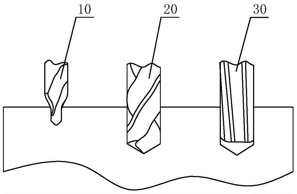
Image


Examples
Embodiment Construction
[0032] The present invention will be further described below in conjunction with the accompanying drawings and embodiments.
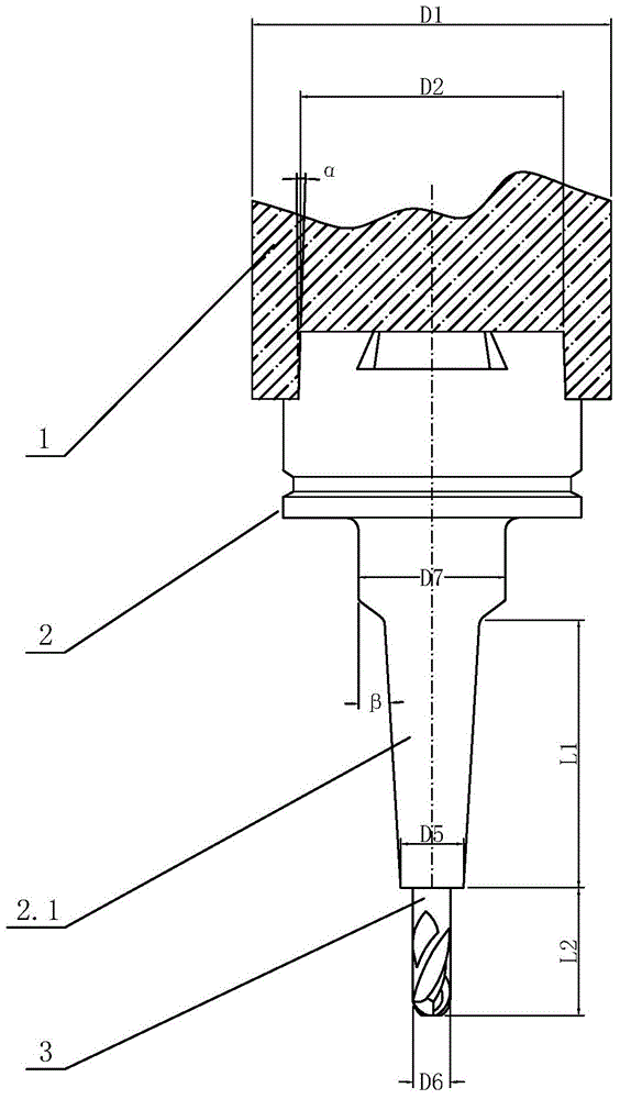
[0033] see image 3 , the tool bar device of this CNC machine tool includes a tool bar 2 connected to the main shaft 1, a cutter head 3 connected to the tool bar 2, the head of the tool bar 2 is inserted in the main shaft 1, and the tail of the tool bar 2 is 2.1 It is in an inverted cone shape, the tail 2.1 is connected to the cutter head 3, and the ratio of the end diameter D5 of the tail 2.1 to the diameter D6 of the cutter head 3 is less than or equal to 1.7:1.
[0034] In this embodiment, the ratio of the diameter D1 of the end of the spindle 1 to the diameter D2 of the head of the tool holder 2 is less than or equal to 1.5:1.
[0035] The taper α of the head of the cutter bar 2 is less than or equal to 2 degrees.
[0036] The taper β of the tail portion 2.1 of the cutter bar 2 is less than or equal to 10 degrees and greater than or equal to 3 deg...
PUM
 Abstract
Description
Claims
Application Information
 - R&D Engineer
- R&D Manager
- IP Professional
- Industry Leading Data Capabilities
- Powerful AI technology
- Patent DNA Extraction
Browse by: Latest US Patents, China's latest patents, Technical Efficacy Thesaurus, Application Domain, Technology Topic, Popular Technical Reports.
© 2024 PatSnap. All rights reserved.Legal|Privacy policy|Modern Slavery Act Transparency Statement|Sitemap|About US| Contact US: help@patsnap.com