Main shaft structure of numerically-controlled machine tool

A technology of CNC machine tools and spindles, which is applied in the direction of metal processing machinery parts, large fixed members, metal processing equipment, etc., can solve problems such as difficult processing and unsatisfactory users, and improve rigidity, surface hardness and peeling resistance. The effect of improving processing efficiency

Inactive Publication Date: 2015-07-22
中山市利群精密实业有限公司
View PDF8 Cites 0 Cited by
  • Summary
  • Abstract
  • Description
  • Claims
  • Application Information

AI Technical Summary

Problems solved by technology

When this kind of CNC gear hobbing machine is working, it is difficult to process small places, which makes users not satisfied

Method used


Image

  • Main shaft structure of numerically-controlled machine tool

Examples


Embodiment Construction

[0019] The present invention will be further described below in conjunction with the accompanying drawings and embodiments.

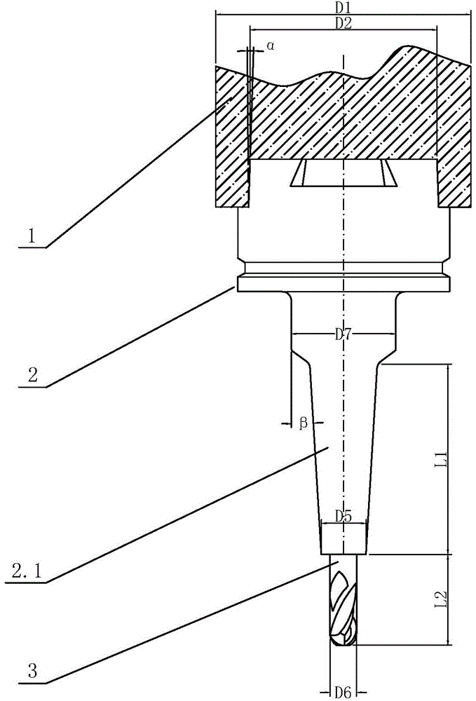
[0020] see figure 1 , the main shaft structure of this CNC machine tool includes a tool bar 2 connected to the main shaft 1, a cutter head 3 connected to the tool bar 2, the head of the tool bar 2 is inserted in the main shaft 1, and the tail 2.1 of the tool bar 2 is in the shape of Inverted cone shape, the tail 2.1 is in contact with the cutter head 3, and the ratio of the end diameter D5 of the tail 2.1 to the diameter D6 of the cutter head 3 is less than or equal to 1.7:1.

[0021] In this embodiment, the ratio of the diameter D1 of the end of the spindle 1 to the diameter D2 of the head of the tool holder 2 is less than or equal to 1.5:1.

[0022] The taper α of the head of the cutter bar 2 is less than or equal to 2 degrees.

[0023] The taper β of the tail portion 2.1 of the cutter bar 2 is less than or equal to 10 degrees and greater than or eq...


PUM


Abstract

The invention provides a main shaft structure of a numerically-controlled machine tool. The main shaft structure comprises a cutter bar connected with a main shaft and a cutter bit connected with the cutter bar. The head of the cutter bar is inserted into the main shaft. The tail of the cutter bar is in an inverted-tapered shape, the tail is connected with the cutter bit, and the specific value of the diameter of the end of the tail and the diameter of the cutter bit is smaller than or equal to 1.7:1. The specific value of the diameter of the end of the main shaft and the diameter of the head of the cutter bar is smaller than or equal to 1.5:1. The taper of the head of the cutter bar is smaller than or equal to 2 degrees. The taper of the tail of the cutter bar is smaller than or equal to 10 degrees and larger than or equal to 3 degrees. The specific value of the length of the tail of the cutter bar and the length of the portion, exposed out of the cutter bar, of the cutter bit is smaller than or equal to 2.5:1. The surface of the cutter bit is covered with an ultramicron layer. The main shaft structure has the advantages of being simple and reasonable in structure, flexible to operate, high in working efficiency and long in service life.

Description

technical field [0001] The invention relates to a spindle structure of a numerically controlled machine tool. Background technique [0002] Chinese Patent Document No. CN 102059408A disclosed a spindle device of a CNC gear hobbing machine on May 18, 2011. The spindle device includes a tool bar assembly, a tool bar assembly clamping mechanism and a tool change mechanism. It consists of a knife, a knife adjusting pad, a shaft sleeve, a lock nut and a knife rod pull stud. The clamping mechanism of the tool bar assembly is composed of a square key and a claw assembly, and the tool changing mechanism is composed of a pull rod, a piston rod, a disc spring, an oil cylinder body, a flange, a bracket, a rotary joint and a limit switch. When this CNC gear hobbing machine is working, it is difficult to process small places, which makes users unsatisfied. Contents of the invention [0003] The object of the present invention is to provide a spindle structure of a numerically control...

Claims


Application Information

Patent Timeline
Patent Type & Authority Applications(China)
IPC IPC(8): B23B19/02
CPCB23Q1/70
Inventor 童章狄
Owner 中山市利群精密实业有限公司
Why Eureka
Try Eureka