
Water-cooled parallel flow heat exchanger with rows of flat pipes

A parallel flow heat exchanger, water-cooled technology, applied in the direction of heat exchanger types, indirect heat exchangers, tubular elements, etc., can solve the problem of reducing the windward area of ​​the heat exchanger, affecting the performance of the device, and inconvenient disassembly and replacement, etc. question

Pending Publication Date: 2021-09-10
ANHUI PROPELLENT HEAT TRANSFER TECH CO LTD
View PDF8 Cites 0 Cited by
  • Summary
  • Abstract
  • Description
  • Claims
  • Application Information

AI Technical Summary

Problems solved by technology

In the present invention, multiple circuits are connected in series, and two rows of flat tubes are stacked together, which reduces the windward area of ​​the heat exchanger, and is suitable for occasions where the installation space is limited and the diameter of the fan is small. However, during use, all the The collecting pipe and the flat pipe are integrated, which is not easy to disassemble and replace
[0006] When the parallel flow heat exchanger in the above patent is in use, it is difficult to ensure high heat exchange efficiency while facilitating splicing and assembly, which affects the performance of the device

Method used


Image

  • Water-cooled parallel flow heat exchanger with rows of flat pipes
  • Water-cooled parallel flow heat exchanger with rows of flat pipes
  • Water-cooled parallel flow heat exchanger with rows of flat pipes

Examples


Embodiment 1

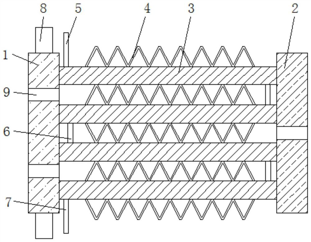
[0042] see Figure 1 to Figure 8 , the present invention provides a technical solution of a water-cooled parallel flow heat exchanger connected with flat tubes: a water-cooled parallel flow heat exchanger connected with flat tubes, including a first header 1 and a 1 side of the second header 2, a number of flat tubes 3 are arranged between the first header 1 and the second header 2, and a number of cooling fins are fixedly installed on the upper and lower end surfaces of the plurality of flat tubes 3 sheet 4, the shape of several heat dissipation fins 4 is triangular, and the heat dissipation fins 4 on both sides of the flat tube 3 are staggered;

[0043] The upper end surface of the first collecting pipe 1 is fixedly equipped with a water inlet pipe 8, and the lower end surface of the first collecting pipe 1 is fixedly installed with a water outlet pipe 16. Both the water inlet pipe 8 and the water outlet pipe 16 are L-shaped, and the water inlet pipe 8 is plugged. Inside th...

Embodiment 2

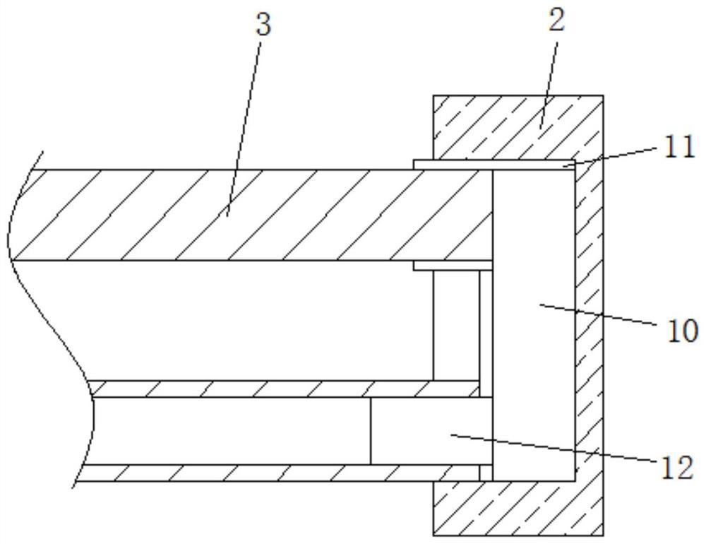
[0052] Such as figure 2 , Figure 4 and Figure 7 As shown, under the situation that other parts are all identical with embodiment 1, the difference between this embodiment and embodiment 1 is:

[0053] The side of the second header 2 is provided with an installation groove 15, and the inside of the installation groove 15 is fixedly installed with a ventilation pipe 10, and the side of the ventilation pipe 10 is fixedly installed with a sleeve pipe 11 and an intubation pipe 12, and the insertion pipe 12 is located at the side of the sleeve pipe 11. Below, and the cross-sectional area of ​​the intubation tube 12 is smaller than the cross-sectional area of ​​the sleeve tube 11, one end of the flat tube 3 is inserted into the inside of the sleeve tube 11, and the other end of the flat tube 3 is sleeved on the intubation tube 12, and the flat tube The end surface of 3 is installed on the corresponding intubation tube 12 or casing 11, so that the flat tube 3 and the correspondin...

Embodiment 3

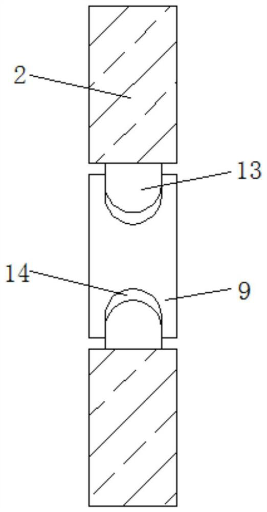
[0057] Such as figure 2 , image 3 and Figure 8 As shown, under the situation that other parts are all identical with embodiment 1, the difference between this embodiment and embodiment 1 is:

[0058] Both ends of the flat tube 3 are provided with a positioning mechanism, the positioning mechanism includes a guide plate 24, the inside of the guide plate 24 is provided with a chute 25, the inside of the chute 25 is slidingly installed with a slide plate 26, and the side of the slide plate 26 is fixedly installed with an extension rod 27. The other end surface of the extension rod 27 is fixedly equipped with a baffle plate 28, and several springs 29 are fixedly installed between the baffle plate 28 and the flat tube 3. The outer surfaces of the baffle plate 28 are all inclined surfaces, which can be convenient for users to It is in contact with the corresponding intubation tube 12 or sleeve tube 11, and the side of the baffle plate 28 far away from the guide plate 24 is prov...


PUM


Abstract

The invention discloses a water-cooled parallel flow heat exchanger with rows of flat pipes and relates to the technical field of heat exchangers. The water-cooled parallel flow heat exchanger comprises a first flow collecting pipe and a second flow collecting pipe positioned on one side of the first flow collecting pipe, wherein the multiple flat pipes are arranged between the first flow collecting pipe and the second flow collecting pipe; a plurality of cooling fins are fixedly mounted on the upper and lower end surfaces of the multiple flat pipes; all the cooling fins are triangular; the cooling fins on both sides of the flat tubes are designed to be staggered; a water inlet pipe is fixedly mounted on the upper end surface of the first flow collecting pipe; a water outlet pipe is fixedly mounted on the lower end surface of the first flow collecting pipe; both the water inlet pipe and the water outlet pipe are L-shaped; the water inlet pipe is inserted into the flat pipe positioned at the top end; the water outlet pipe is connected in a sleeving manner onto one end of the flat pipe positioned at the bottom end; and an air inlet pipe is fixedly mounted at the position, close to one side, of the upper end surface of the flat pipe positioned at the top end, so that the heat exchange efficiency of the heat exchanger can be improved while the heat exchanger is convenient to assemble, and then the use performance of the heat exchanger can be improved.

Description

technical field [0001] The invention relates to the technical field of heat exchangers, in particular to a water-cooled parallel flow heat exchanger with flat tubes connected in rows. Background technique [0002] Parallel flow heat exchanger is an all-aluminum heat exchanger with compact structure, high heat exchange efficiency, and cost advantage compared with ordinary copper tube heat exchanger, and has been paid more and more attention by various air-conditioning manufacturers. Ideally, the refrigerant should be evenly distributed into each flat tube of the parallel flow heat exchanger to ensure the best heat transfer efficiency of the parallel flow heat exchanger. [0003] The headers of parallel flow heat exchangers are usually produced in a thin cylindrical structure. At the same time, in order to reduce production costs, the refrigerant distribution method mostly adopts internal split flow. Because the external flow requires the assistance of a flow divider, a distr...

Claims


Application Information

Patent Timeline
Patent Type & Authority Applications(China)
IPC IPC(8): F28D7/10F28F1/34
CPCF28D7/10F28F1/34
Inventor 张志峰胡西芹刘红军张凌霞
Owner ANHUI PROPELLENT HEAT TRANSFER TECH CO LTD
Learn More