Independently disassembled and assembled decorative curtain wall and component assembly thereof
A curtain wall and component technology, which is applied in the field of decorative curtain wall and its component assembly, and can solve indoor stuffiness, pollution and other problems
- Summary
- Abstract
- Description
- Claims
- Application Information
AI Technical Summary
Problems solved by technology
Method used
Image
Examples
Embodiment 1
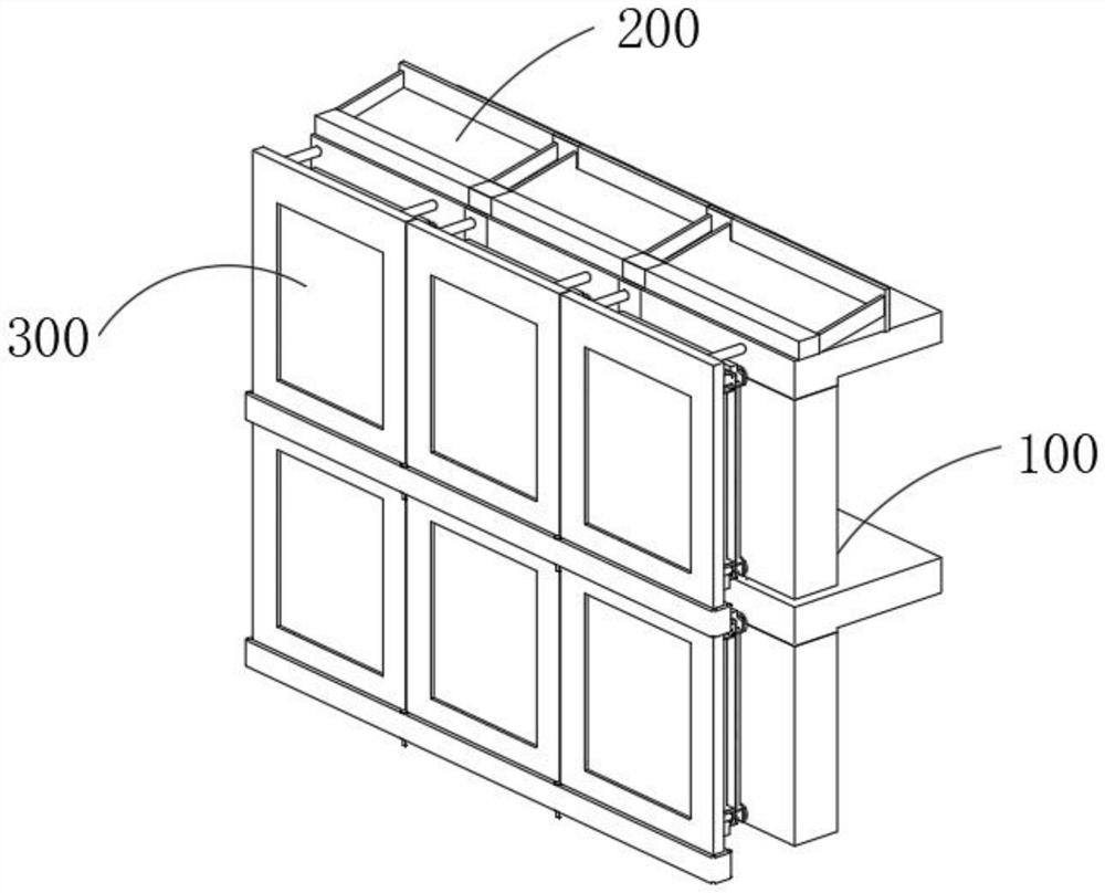
[0051] combine figure 1 , 4 , 5 and 6, an independently disassembled decorative curtain wall and its component assembly provided by the present invention include a building exterior wall 100, a water collecting device 200 and a decorative curtain wall 300, and a plurality of grooves are provided inside the building exterior wall 100 hole, the water collecting device 200 is assembled in the slot opened on the building exterior wall 100, the decorative curtain wall 300 is divided into two structures of the installation assembly 310A and the curtain wall assembly 320A, the installation assembly 310A includes the installation plate 310, the The fixed plate 320, the circulation device 330 fixed on the inner side of the fixed plate 320, the battery assembly 340 assembled at the lower end of the fixed plate 320, the water pump 350 installed under the battery assembly 340 and the connection assembly 360 fixed at the bottom of the battery assembly 340, through The installation plate 3...
Embodiment 2
[0054] combine Figure 7 and 8 As shown, on the basis of Embodiment 1, the fixing plate 320 includes a top plate 321 assembled on the lower end of the mounting bracket 312, a fixing piece 322 fixed on the top plate 321, a limit strip 323 assembled on the lower end of the fixing piece 322 and The long tube 324 and the fixed plate 320 are conveniently connected with the installation frame 317 and the clamping plate 341 to form a closed cavity through the long tube 324 inside the limit bar 323. Tube 316 is connected through.
[0055] Assembled on the outer horizontal plate 331 of the limiting bar 323, the horizontal groove 332 set on the inner side of the horizontal plate 331, the sponge block 333 arranged on the horizontal groove 332, the fixing part 2 334 fixed on the outside of the limiting bar 323 and the horizontal groove 334 set on the horizontal The chute 335 inside the plate 331, the water source in the closed cavity is evaporated to form water vapor after being irradia...
Embodiment 3
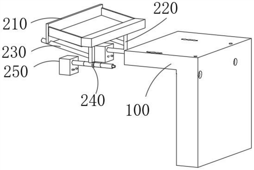
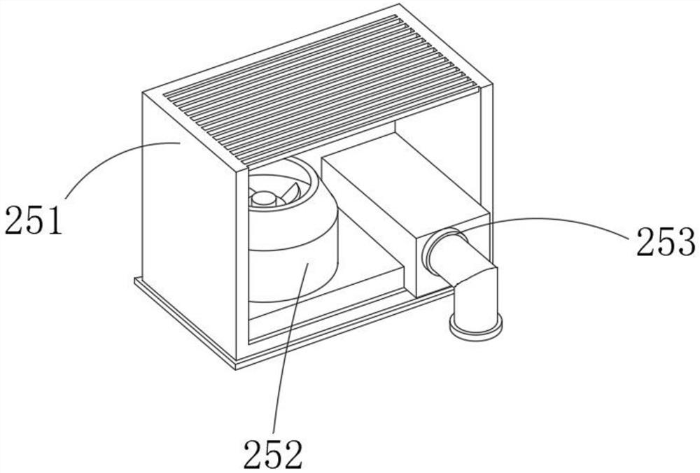
[0060] combine figure 2 and 3 As shown, in the above-mentioned embodiment, the water collection device 200 includes a sump 210 fixed on the exterior wall 100 of the building, a water delivery pipe 220 assembled at the bottom of the sump 210 , and a water guide pipe 230 pierced in the exterior wall 100 of the building. 1. The connecting pipe 2 315 installed in the building exterior wall 100 and the heat collector 250 assembled at one end of the connecting pipe 315. In order to reduce the consumption of water, the water collecting device 200 is arranged on the top of the building. When it rains, the rainwater Flow along the slope of the sump 210 into the water pipe 220, and the accumulated water on the roof will also flow into the water pipe 220 along the water pipe 230, and the rainwater can be collected and discharged into the installation assembly 310A conveniently by setting the water collection device 200. The water delivery pipe 220 assembled under the sump 210 communica...
PUM
 Abstract
Description
Claims
Application Information
 - R&D
- Intellectual Property
- Life Sciences
- Materials
- Tech Scout
- Unparalleled Data Quality
- Higher Quality Content
- 60% Fewer Hallucinations
Browse by: Latest US Patents, China's latest patents, Technical Efficacy Thesaurus, Application Domain, Technology Topic, Popular Technical Reports.
© 2025 PatSnap. All rights reserved.Legal|Privacy policy|Modern Slavery Act Transparency Statement|Sitemap|About US| Contact US: help@patsnap.com


