
Forming method for cutting edge of shutter punch of air conditioner die

A molding method and shutter technology, applied in abrasive surface adjustment devices, other manufacturing equipment/tools, parts of grinding machine tools, etc., can solve the problems of unsuitable batch parts processing and production, long processing cycle, increasing processing difficulty, etc. The effect of reducing the difficulty of processing, good forming effect and simple processing

Pending Publication Date: 2021-09-03
WUXI MICRO RES
View PDF9 Cites 0 Cited by
  • Summary
  • Abstract
  • Description
  • Claims
  • Application Information

AI Technical Summary

Problems solved by technology

At present, the cutting edge is mainly formed by slow wire processing or optical curve grinding. Both methods are in the form of point processing, and the forming is slow, and the stamping teeth with small spacing increase the processing difficulty, high process requirements, and processing cycle. Long, not suitable for processing and production of batch parts

Method used


Image

  • Forming method for cutting edge of shutter punch of air conditioner die
  • Forming method for cutting edge of shutter punch of air conditioner die
  • Forming method for cutting edge of shutter punch of air conditioner die

Examples


Embodiment Construction

[0022] The technical solutions of the present invention will be further described below in conjunction with the accompanying drawings and through specific implementation methods.

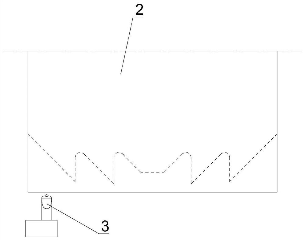
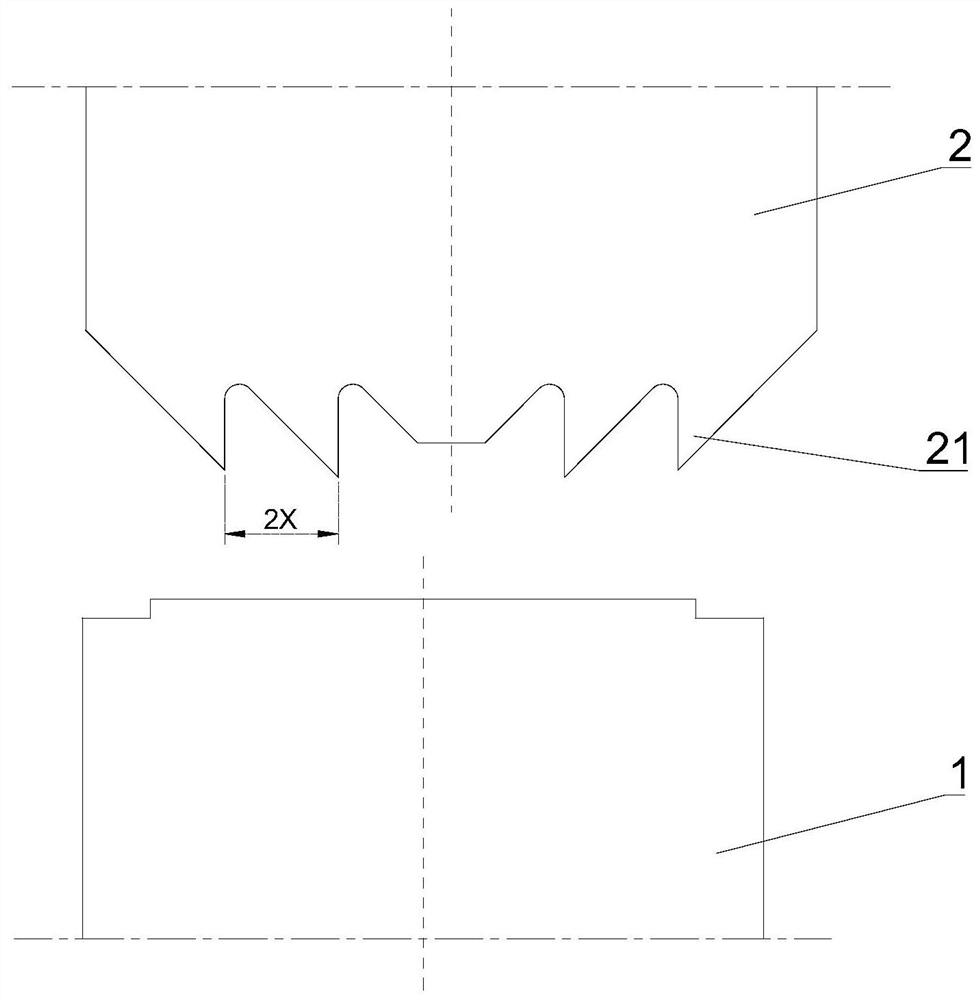
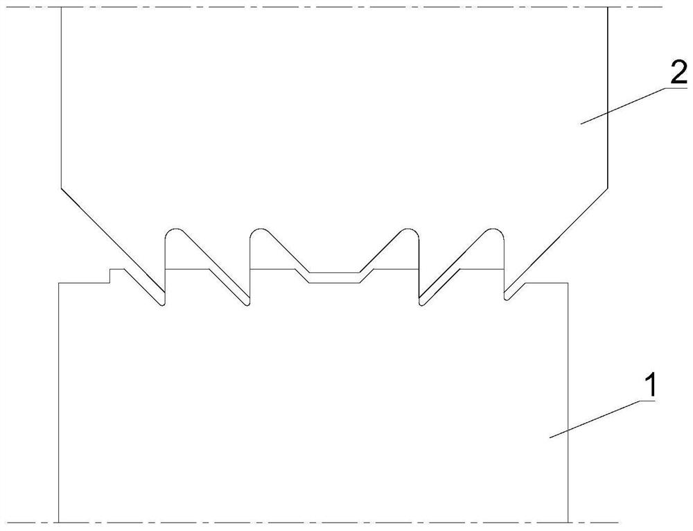
[0023] This embodiment provides a method for forming the edge of the louver punch of an air-conditioning mold. Specifically, the lower punch of the louver in an air-conditioning mold is used as an example. On this basis, the upper punch and other similar punch structures are applicable.

[0024] A plurality of stamping teeth 11 are arranged at intervals on the cutting edge of the punch, and the stamping teeth 11 on both sides are mirror-image symmetrical. There are m stamping teeth 11 on one side (m=2, 3, 4, ...), and the tooth spacing is X . In this embodiment, a total of eight stamping teeth on the cutting edge and four stamping teeth on each side are taken as an example to further illustrate the forming process. The processing steps are as follows:

[0025] Step 1: According to the shape of the ...


PUM


Abstract

The invention discloses a forming method for a cutting edge of a shutter punch of an air conditioner die. A plurality of punching teeth are arranged on the cutting edge at intervals, the punching teeth on the two sides are in mirror symmetry, the number of the punching teeth on the single side is m, and the distance between the punching teeth is X. The forming method comprises the steps that corresponding grinding teeth are designed on a grinding wheel profile according to the shapes of the punching teeth on the cutting edge, at least one pair of grinding teeth are arranged in a mirror image manner; a formed grinding wheel with a target profile is trimmed through a diamond pen; and the surface of a punch block is directly ground by the forming grinding wheel, grinding is carried out in several times, the grinding wheel transversely deviates by the Y distance relative to the punch block every time, and therefore the target cutting edge shape is formed. According to the forming method for the cutting edge of the shutter punch of the air conditioner die, the forming grinding wheel is used for grinding the punch block, rapid forming is achieved in a linear machining mode, machining is easy, the efficiency is high, the forming effect is good, the final shape is obtained through multiple times of offset grinding especially under the situation that the tooth space is small, the grinding wheel machining difficulty is reduced, and the method is particularly suitable for batch part machining and production.

Description

technical field [0001] The invention relates to a mold for processing louver parts, in particular to a method for forming the edge of a louver punch in an air-conditioning mold. Background technique [0002] Such as Figure 6 Shown is the structural diagram of the louver punch in an air-conditioning mold, and the shape of the cutting edge is as follows Figure 7 As shown, the cutting edge is characterized by multiple stamping teeth symmetrically arranged on both sides, and the tooth spacing is small. At present, the cutting edge is mainly formed by slow wire processing or optical curve grinding. Both methods are in the form of point processing, and the forming is slow, and the stamping teeth with small spacing increase the processing difficulty, high process requirements, and processing cycle. Long, not suitable for processing and production of batch parts. Therefore, need further improvement. Contents of the invention [0003] The object of the present invention is to ...

Claims


Application Information

Patent Timeline
Patent Type & Authority Applications(China)
IPC IPC(8): B24B3/60B24B41/06B24B53/07
CPCB24B3/60B24B41/06B24B53/07
Inventor 卢其欢蔡磊明陈亮姚新飞匡忠健
Owner WUXI MICRO RES
Learn More