
Shield gate trench field effect transistor structure and preparation method thereof

A field effect transistor and shielded gate technology, which is applied in the field of shielded gate trench field effect transistor structure and its preparation, can solve the problems of complex preparation process, asynchronous on and off states of the shielded gate trench field effect transistor, etc. Simple process steps, avoid asynchronous turn-on and turn-off states, reduce the effect of gate-drain capacitance

Pending Publication Date: 2021-08-24
瑶芯微电子科技(上海)有限公司
View PDF0 Cites 1 Cited by
  • Summary
  • Abstract
  • Description
  • Claims
  • Application Information

AI Technical Summary

Problems solved by technology

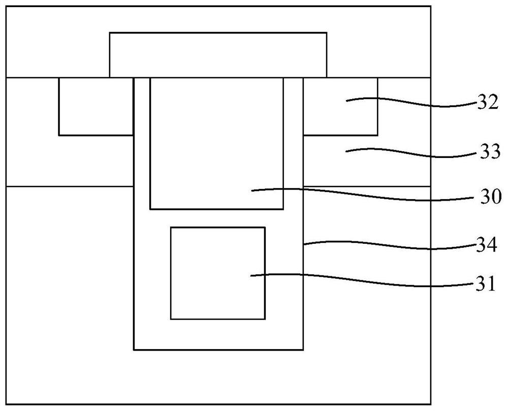
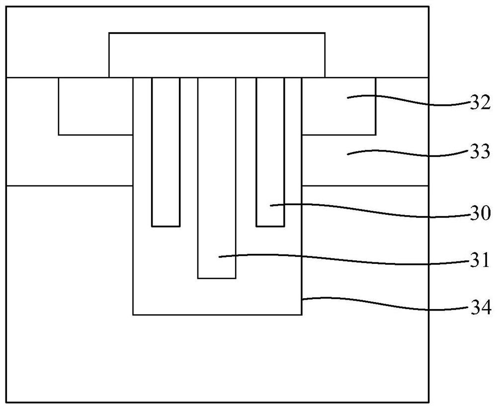
[0004] In view of the shortcomings of the prior art described above, the purpose of the present invention is to provide a shielded gate trench field effect transistor structure and its preparation method, which is used to solve the problem of the preparation process of the shielded gate trench field effect transistor with the upper and lower structures in the prior art. Complex, and shielded gate trench field effect transistors with left and right structures have problems such as asynchronous turn-on and turn-off states

Method used


Image

  • Shield gate trench field effect transistor structure and preparation method thereof
  • Shield gate trench field effect transistor structure and preparation method thereof
  • Shield gate trench field effect transistor structure and preparation method thereof

Examples


Embodiment Construction

[0077] Embodiments of the present invention are described below through specific examples, and those skilled in the art can easily understand other advantages and effects of the present invention from the content disclosed in this specification. The present invention can also be implemented or applied through other different specific implementation modes, and various modifications or changes can be made to the details in this specification based on different viewpoints and applications without departing from the spirit of the present invention.

[0078] see Figure 3 to Figure 17 . It should be noted that the diagrams provided in this embodiment are only schematically illustrating the basic idea of ​​the present invention, so that only the components related to the present invention are shown in the diagrams rather than the number, shape and Dimensional drawing, the type, quantity and proportion of each component may be changed according to actual needs during actual implemen...


PUM


Abstract

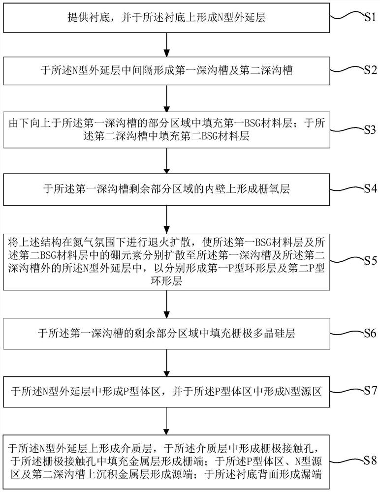
The invention provides a shield gate trench field effect transistor structure and a preparation method thereof. The first deep grooves and the second deep grooves are arranged in different deep grooves at intervals, so that the problem that the transistor is not synchronously turned on or turned off is avoided, and a plurality of resistors RDS (on) with the same resistance are connected in parallel; the total resistance is equivalent to RDS (on) / n, and n is the number of cells, so that the on-resistance is greatly reduced, and the static loss of the device is reduced; the bottom region of the first deep groove is filled with a BSG material, so the gate-drain overlapping area of the device is reduced, the gate-drain capacitance is reduced, the switching speed of the device is improved, and the dynamic loss of the device is reduced; the first P-type annular layer and the second P-type annular layer are respectively depleted with the N-type epitaxial layer, and the depletion layers of the adjacent first deep trench and second deep trench are communicated with each other along with the increase of the voltage, so that the drain-source leakage current Idss of the device is further reduced, the static loss of the device is reduced, and the soft breakdown is prevented; and the process steps are simple and the cost is low.

Description

technical field [0001] The invention belongs to the field of semiconductor device design and manufacture, and in particular relates to a structure of a shielded gate trench field effect transistor and a preparation method thereof. Background technique [0002] With the continuous development of semiconductor technology, the structure of metal oxide semiconductor field effect transistor (MOSFET) has also been continuously improved. Shielded gate trench field effect transistor (Split Gate Trench MOSFET, referred to as SGT-MOSFET) is one of the improved structures. By introducing a shielded gate structure, the gate-drain overlap area of ​​the device is reduced, thereby reducing the gate-drain capacitance to increase the switching speed. The purpose of reducing the dynamic loss of the device. Therefore, shielded gate trench MOS devices are widely used in various power electronic systems. [0003] At present, the shielded gate trench field effect transistor is divided into two ...

Claims


Application Information

Patent Timeline
IPC IPC(8): H01L29/78H01L29/06H01L29/423H01L21/336H01L21/28
CPCH01L21/28035H01L29/0607H01L29/0684H01L29/4236H01L29/66484H01L29/66666H01L29/7827H01L29/7831
Inventor 郭亮良
Owner 瑶芯微电子科技(上海)有限公司
Learn More