Heat conductive member and method for manufacturing same

A technology of heat-conducting components and manufacturing methods, which is applied in the field of heat-conducting components and their manufacturing, can solve problems such as performance degradation of thermal components, and achieve the effect of reducing shedding

Inactive Publication Date: 2021-08-24
NIPPON DENSAN CORP +1
View PDF8 Cites 0 Cited by
  • Summary
  • Abstract
  • Description
  • Claims
  • Application Information

AI Technical Summary

Problems solved by technology

[0005] Furthermore, if the block of the material constituting the liquid-absorbent core structure, that is, the material sheet fal...

Method used


Image

  • Heat conductive member and method for manufacturing same
  • Heat conductive member and method for manufacturing same
  • Heat conductive member and method for manufacturing same

Examples


Embodiment Construction

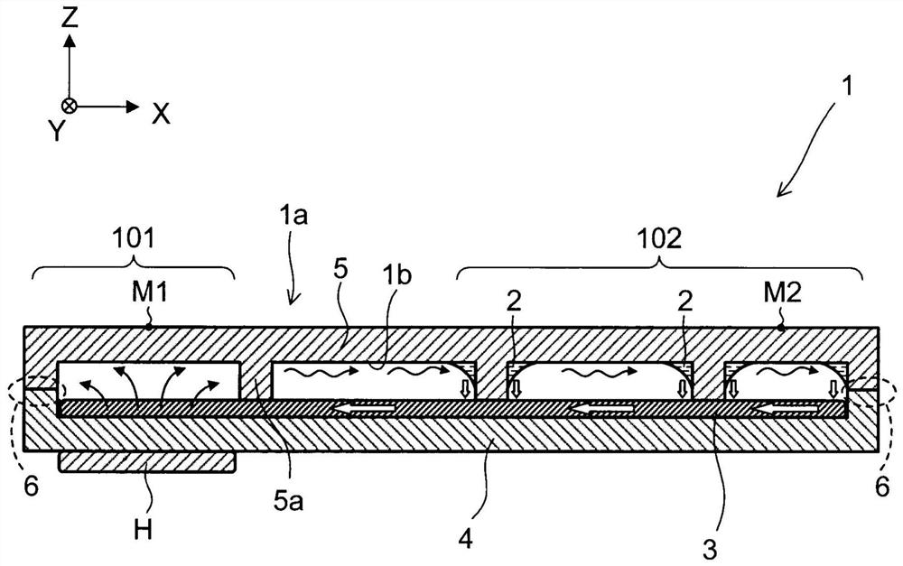
[0018] Hereinafter, a vapor chamber 1 as a heat conduction member according to an exemplary embodiment of the present invention will be described in detail with reference to the accompanying drawings. It should be noted that, in the drawings, the XYZ coordinate system is appropriately shown as a three-dimensional orthogonal coordinate system. In the XYZ coordinate system, the Z-axis direction indicates the vertical direction (that is, the up-down direction), the +Z direction indicates the upper side (opposite the direction of gravity), and the -Z direction indicates the lower side (the direction of gravity). The Z-axis direction may be the facing direction of the first metal plate 4 and the second metal plate 5 described later. The X-axis direction refers to a direction perpendicular to the Z-axis direction, and the one direction and the opposite direction are referred to as +X direction and −X direction, respectively. The Y-axis direction refers to a direction perpendicular ...


PUM

PropertyMeasurementUnit
Thicknessaaaaaaaaaa
Particle sizeaaaaaaaaaa

Abstract

Provided are a heat transfer member and a method for manufacturing the same. The heat transfer member is provided with a case that accommodates a working medium and a porous wick structure that transports the working medium. The liquid-absorbing core structure has a thickness of 0.02 mm or more and 0.1 mm or less, and has a void ratio of 51% or more and 80% or less. The housing has a first metal plate that supports the wick structure. The liquid-absorbing core structure includes: a surface layer portion located at a position away from the first metal plate; and a main body part located between the surface layer part and the first metal plate. The surface layer portion has a different structure from the main body portion.

Description

technical field [0001] The present invention relates to a heat conducting member and a manufacturing method thereof. Background technique [0002] Conventionally, heat pipes have been proposed as heat transfer members. A working medium such as water and a liquid-absorbing core structure are sealed inside the heat pipe. When the heat pipe is placed in contact with the heat generating body, the working medium inside is heated by the heat generating body to be vaporized. The evaporated steam moves to the heat release side inside the heat pipe, thereby transferring heat. On the exothermic side, the vapor is cooled by exothermic heat and liquefied. The liquid working medium moves toward the heat generating body in the liquid-absorbent wick structure by capillary action. Through this movement of the working medium, heat is transferred from the heat generating body side to the heat radiation side. [0003] For example, as in International Publication No. WO2017 / 056842, the liq...

Claims


Application Information

Patent Timeline
IPC IPC(8): F28D15/04
CPCF28D15/046F28D15/0275
Inventor 萩原悠治多田清志
Owner NIPPON DENSAN CORP
Why Eureka
Try Eureka