A kind of iron-rich nanobelt oxygen evolution electrocatalyst and preparation method thereof
An electrocatalyst, nanobelt technology, applied in nanotechnology, nanotechnology, nanotechnology for materials and surface science, etc., can solve the problems of poor iron-based OER catalyst activity, increase catalyst production cost, etc., and achieve excellent OER catalysis performance, reduction of overpotential and energy consumption, effect of short growth cycle
- Summary
- Abstract
- Description
- Claims
- Application Information
AI Technical Summary
Problems solved by technology
Method used
Image

Examples
Embodiment 1
[0041] The nickel foam with a length of 20 mm and a width of 5 mm was ultrasonically cleaned with acetone, 1M HCl, absolute ethanol and deionized water for 30 minutes to remove surface impurities. The iron foam of the same size was ultrasonically cleaned with acetone, absolute ethanol and deionized water for 30 minutes in order to remove impurities on the surface. The above-mentioned foamed nickel is connected with the foamed iron with a wire.
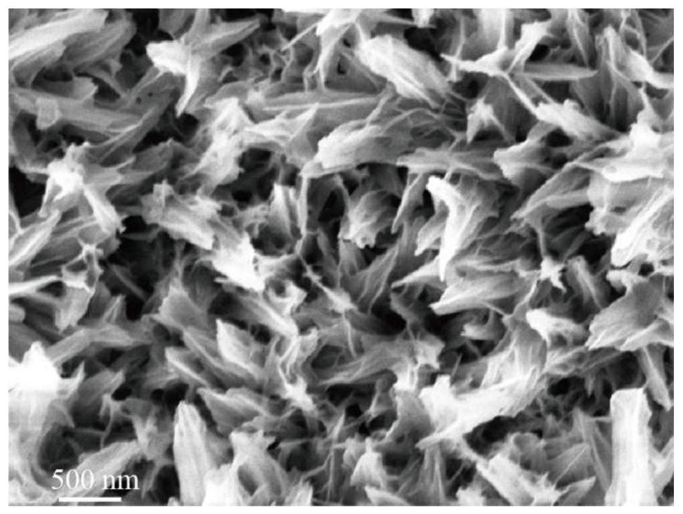
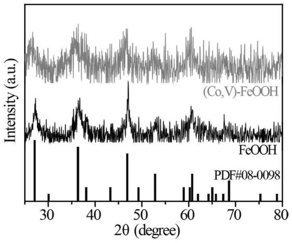
[0042] Add 20 mL of 1M NaCl, 18.2 mL of 5 mM CoCl to the reactor 2 ·6H 2 O and 1.8 mL of 5 mM VCl 3 . i.e. CoCl 2 ·6H 2 O and VCl 3 The volume ratio is 10:1. The reaction was carried out at room temperature and stirring for 8 hours, and after the reaction was completed, a (Co, V)-FeOOH nanometer charged catalyst was obtained. The nanosheet morphology of (Co, V)-FeOOH was obtained by scanning electron microscopy, as figure 1 shown. The crystal structure of (Co, V)-FeOOH was obtained by X-ray diffraction, such as figure 2 As ...
Embodiment 2
[0044]The experimental process is the same as in Example 1, and the change is that the electrolyte is respectively composed of 20mL of 1M NaCl and 20mL of 5mM CoCl 2 ·6H 2 O composition. After the reaction, a Co-FeOOH nanocharged catalyst with a small amount of Co-modified FeOOH matrix was obtained. The nanosheet morphology of Co-FeOOH was obtained by scanning electron microscopy, such as Figure 4 shown. The crystal structure of Co-FeOOH was obtained by X-ray diffraction, such as Figure 5 , indicating that a small amount of Co doping did not cause changes in the crystal structure.
Embodiment 3
[0046] The experimental process is the same as in Example 1, and the change is that the electrolyte is respectively composed of 20mL of 1M NaCl and 20mL of 5mM VCl 3 constitute. After the reaction, a small amount of V-FeOOH nano-charged catalyst with V-modified FeOOH matrix was obtained. The morphology of nanosheets of V-FeOOH was obtained by scanning electron microscopy, such as Figure 6 shown. The crystal structure of V-FeOOH was obtained by X-ray diffraction, such as Figure 7 , indicating that a small amount of V doping did not cause changes in the crystal structure.
PUM
| Property | Measurement | Unit |
|---|---|---|
| electric potential / voltage | aaaaa | aaaaa |
| length | aaaaa | aaaaa |
| width | aaaaa | aaaaa |
Abstract
Description
Claims
Application Information
 - R&D
- Intellectual Property
- Life Sciences
- Materials
- Tech Scout
- Unparalleled Data Quality
- Higher Quality Content
- 60% Fewer Hallucinations
Browse by: Latest US Patents, China's latest patents, Technical Efficacy Thesaurus, Application Domain, Technology Topic, Popular Technical Reports.
© 2025 PatSnap. All rights reserved.Legal|Privacy policy|Modern Slavery Act Transparency Statement|Sitemap|About US| Contact US: help@patsnap.com