
Method for predicting residual life of gearbox bearing

A prediction method, gear box technology, applied in neural learning methods, testing of mechanical components, testing of machine/structural components, etc., can solve the inaccurate life prediction results, do not consider other types such as current signal sensors, do not consider To solve problems such as the results of the coupling effect of components, to achieve the effect of strengthening feature extraction and screening capabilities, improving prediction accuracy, and avoiding deep damage

Active Publication Date: 2021-08-13
YANSHAN UNIV
View PDF9 Cites 0 Cited by
  • Summary
  • Abstract
  • Description
  • Claims
  • Application Information

AI Technical Summary

Problems solved by technology

[0004] Most of the existing studies only focus on the single-channel signal of a single sensor to extract the degradation features of components, without considering that the degradation of components is the result of the coupling of various parts. for a comprehensive information space
The current bearing life prediction research based on multi-channel signals only performs feature extraction and degradation state modeling analysis based on a single vibration, without considering other types of sensors such as current signals. However, only relying on a single type of sensor signal is not enough to accurately describe Potential degradation mechanisms of the system, leading to inaccurate lifetime predictions

Method used


Image

  • Method for predicting residual life of gearbox bearing
  • Method for predicting residual life of gearbox bearing
  • Method for predicting residual life of gearbox bearing

Examples


Embodiment Construction

[0037] Below in conjunction with embodiment the present invention is described in further detail:

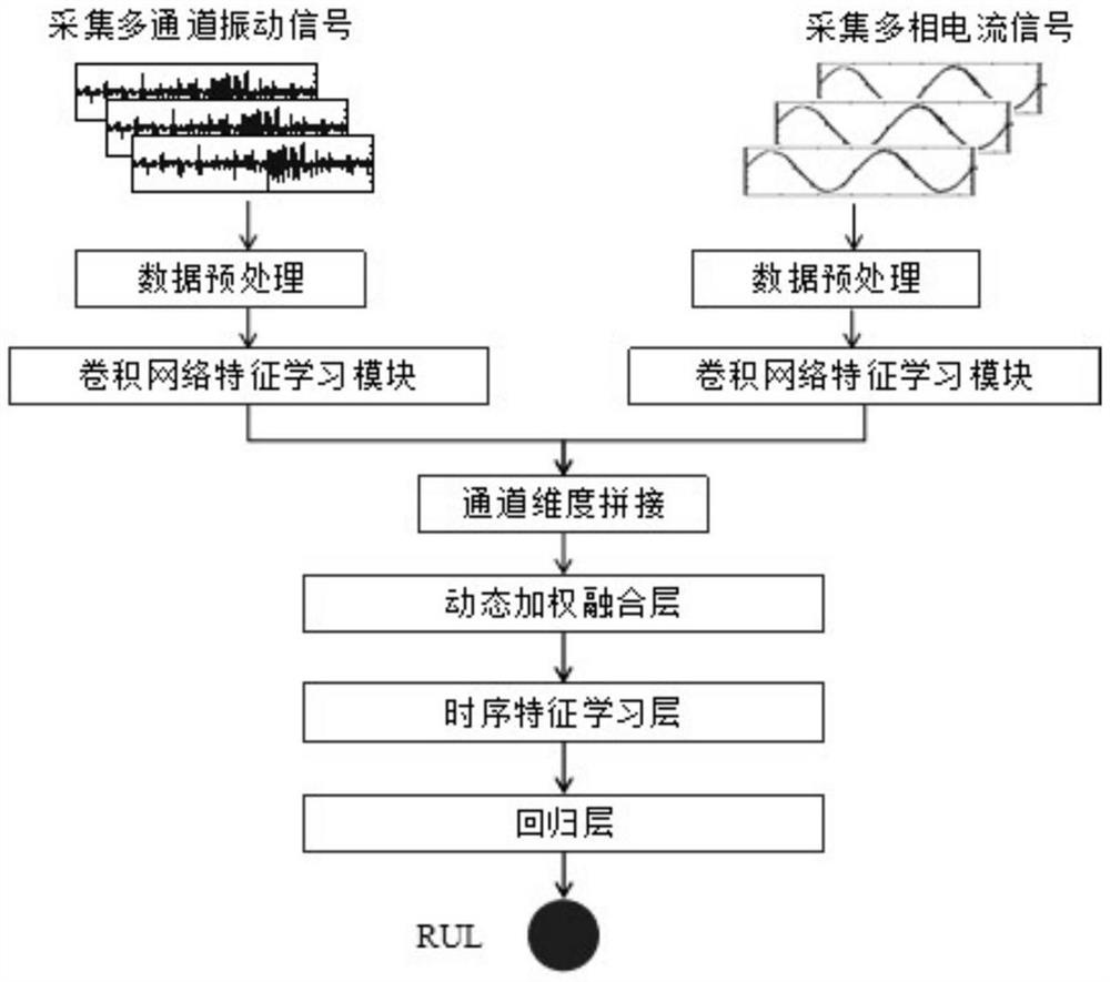
[0038] Such as figure 1 As shown, a method for predicting the remaining life of gearbox bearings includes the following steps:

[0039] Step S1: Step S11, use the acceleration sensor to collect the multi-channel vibration signal of the gearbox bearing, obtain the multi-channel stator current signal from the generator output terminal through the current clamp, obtain the original multi-channel vibration signal and the multi-channel stator current signal, and perform data preprocessing;

[0040] Step S12, perform equidistant indexing on the data in time series to reduce the amount of data, and the step size is M;

[0041] Step S13, perform sliding window processing to fully extract time series feature information, the window size is W, and after further normalization processing of maximum and minimum values, the finally obtained data size is:

[0042] N 1 / (M*W)×1×D 1 ,N 2 / ...


PUM


Abstract

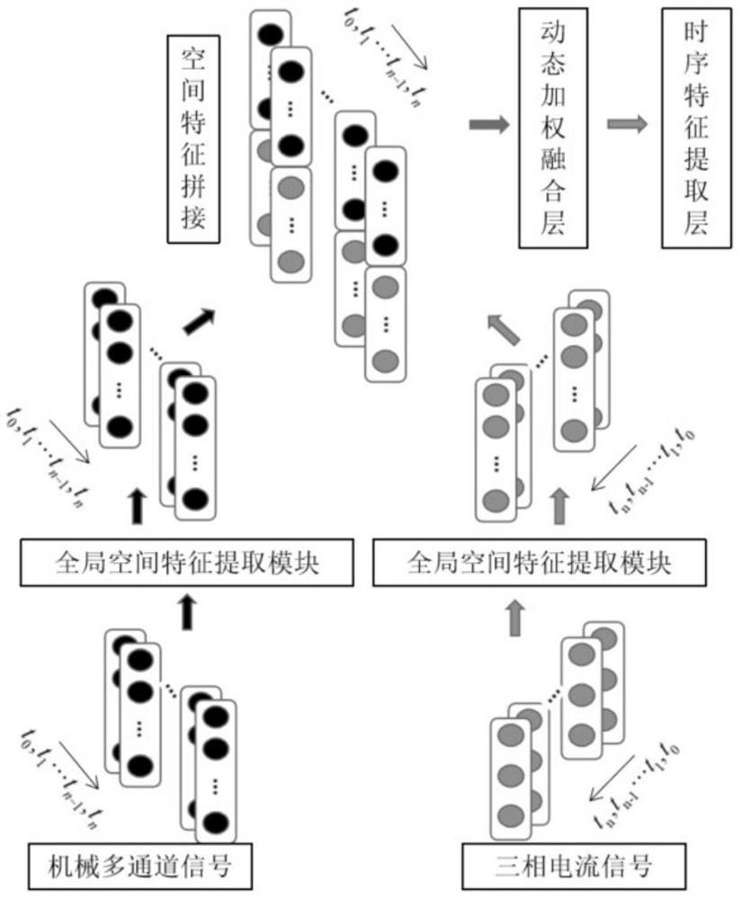
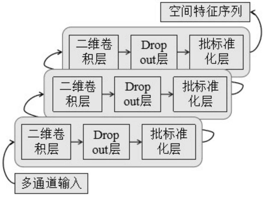
The invention discloses a method for predicting the residual life of a gearbox bearing, and the method comprises the steps of collecting a multi-channel vibration signal of the gearbox bearing through an acceleration sensor, obtaining a multi-channel stator current signal from an output end of a generator through a current clamp, obtaining an original multi-channel vibration signal and an original multi-channel stator current signal, and carrying out the data preprocessing; designing a convolutional network spatial feature extraction module, respectively extracting the spatial features of the vibration signals and the current signals, and splicing the spatial features on a channel dimension; designing a dynamic weighted fusion layer, and fusing the spatial features of the vibration signal and the current signal; and extracting the time sequence features from a fused time sequence feature vector sequence through a bidirectional long and short time memory network, and finally predicting the residual life of the bearing through a regression layer. According to the invention, the space-time correlation feature information between vibration and current can be adaptively learned and dynamically fused, and the degradation feature extraction capability and the life prediction precision are improved.

Description

technical field [0001] The invention relates to the technical field of prediction of the remaining life of a gear box bearing of a wind power generating set, in particular to a method for predicting the remaining life of a gear box bearing. Background technique [0002] The gearbox is an important part of a large doubly-fed wind turbine and the key to energy transfer and conversion. In practice, it is not only one of the key systems for the safe operation of wind turbines, but also one of the main sources of frequent failures of wind turbines. The internal structure of the gearbox is complex. Under the long-term working conditions of low speed, heavy load, alternating load and strong gust impact, key components such as bearings are prone to wear and performance degradation, and even evolve into serious failures until failure. Dealing with the failure of key components such as bearings may trigger a chain reaction, leading to the shutdown of the entire system, resulting in h...

Claims


Application Information

Patent Timeline
IPC IPC(8): G06F30/27G01M13/045G06N3/04G06N3/08G06F119/04
CPCG06F30/27G01M13/045G06N3/08G06F2119/04G06N3/044G06N3/045Y02E10/72
Inventor 江国乾周文达谢平李小俚赵小川李英伟李陈
Owner YANSHAN UNIV
Learn More