Zero-leakage non-friction composite seal for rotating shaft
A composite sealing and non-friction technology, which is applied in the direction of engine sealing, clutch, mechanical drive clutch, etc., can solve the problems of increasing stern shaft torque and power loss, easy leakage of sealing oil of stern shaft tube, pollution of rivers, lakes and sea water, etc. , achieve the effect of reducing maintenance cost, improving work efficiency and reducing failure risk
- Summary
- Abstract
- Description
- Claims
- Application Information
AI Technical Summary
Problems solved by technology
Method used
Image

Examples
Embodiment 1
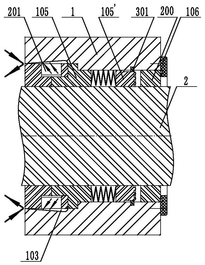
[0077] See attached figure 1 , from left to right are centrifugal impeller 201, fixed end plate 105, moving end plate 105', sealing ring seat 200 and baffle plate 106, positioning pin 301 is set between moving end plate 105' and the inner cavity of sealed cabin 1, centrifugal impeller 201 is located in the working chamber 103, wherein the inner ring of the blades of the centrifugal impeller 201 wraps the axially extending outer end of the fixed end plate 105; the baffle plate 106 fixed on the end face of the airtight cabin 1 is a flexible non-metallic material, mainly to intercept the air Dust, during the rotation of the rotating shaft 2, there is slight friction between the baffle plate 106 and the corresponding end surface of the sealing ring seat 200.
[0078] attached figure 1 As shown, at this time, the rotating shaft 2 is rotating, and the centrifugal impeller 201 rotates synchronously to prevent the fluid from entering the inner cavity of the sealed chamber 1. The bloc...
Embodiment 2
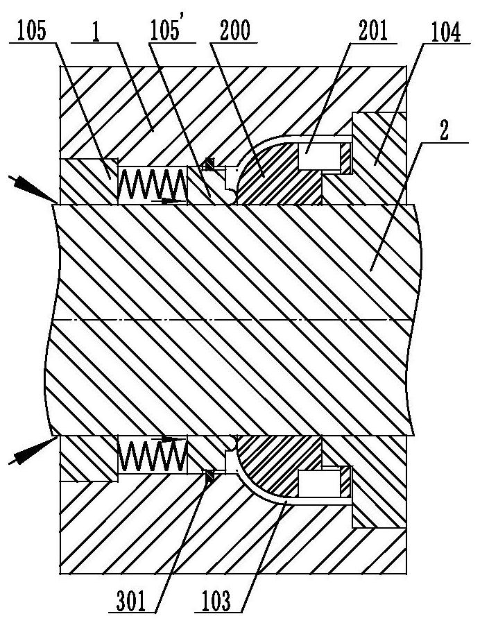
[0084] See attached figure 2 , from left to right are the fixed end plate 105, the moving end plate 105′, the sealing ring seat 200, the centrifugal impeller 201, and the end plate 104. The ring wraps around the axially extending outer ends of adjacent end plates 104 .
[0085] attached figure 2 As shown, at this moment, the rotating shaft 2 and the centrifugal impeller 201 stop rotating, and the pressure of the fluid pushes the sealing end surface of the moving end plate 105 ′ to always be in close contact with the sealing end surface of the sealing ring seat 200 .
Embodiment 3
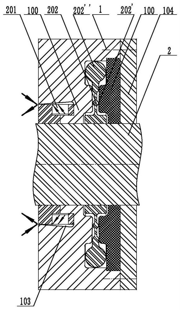
[0087] See attached image 3 , from left to right are the centrifugal impeller 201, the spacer 100, the flywheel clutch (including the shaft sleeve fixed on the rotating shaft 2, the middle ring 202 with a sealing ring platform B202', the ring hammer 202"), the spacer 100, the end plate 104 , wherein the inner ring of the blades of the centrifugal impeller 201 wraps the axially extending outer ends of the adjacent partitions 100 .
[0088] attached image 3 As shown, at this time, the rotating shaft 2 is rotating, and the pressure generated by the synchronous rotation of the centrifugal impeller 201 is greater than the infiltration pressure of the fluid, preventing the fluid from entering the inner cavity of the sealed cabin 1. During the synchronous rotation of the flywheel clutch, at the same time, due to the gravity of the ring hammer 202 " , the sealing end surface of the middle ring 202 is away from the sealing end surface of the spacer 100 .
PUM
 Abstract
Description
Claims
Application Information
 - R&D
- Intellectual Property
- Life Sciences
- Materials
- Tech Scout
- Unparalleled Data Quality
- Higher Quality Content
- 60% Fewer Hallucinations
Browse by: Latest US Patents, China's latest patents, Technical Efficacy Thesaurus, Application Domain, Technology Topic, Popular Technical Reports.
© 2025 PatSnap. All rights reserved.Legal|Privacy policy|Modern Slavery Act Transparency Statement|Sitemap|About US| Contact US: help@patsnap.com