


Quick Research
Generate reliable direction feasibility study reports for your R&D in just a few steps.

Technical Q&A
Discover and master advanced knowledge NOW. Basics, ideas, possibilities, all at once.

Find Solutions
As an expert in R&D theories, this can generate solutions to your technical problems instantly.

Evaluate Feasibility
Analyze your overall solution with one click, know your potential R&D risks in advance.

Monitor Landscape
Get weekly tech updates, stay abreast of the latest tech innovations and key insights.
Rotating shaft composite seal containing annular spring piece clutch
A ring-shaped spring and composite sealing technology, applied in clutches, friction clutches, engine seals, etc., can solve the problems of increasing stern shaft torque and power loss, easy leakage of sealing oil of stern shaft tubes, water pollution of rivers, lakes and seas, etc. Achieve the effect of reducing maintenance costs, improving work efficiency, and reducing the risk of failure
- Summary
- Abstract
- Description
- Claims
- Application Information
AI Technical Summary
Problems solved by technology
Method used
Image

Examples
Embodiment 1
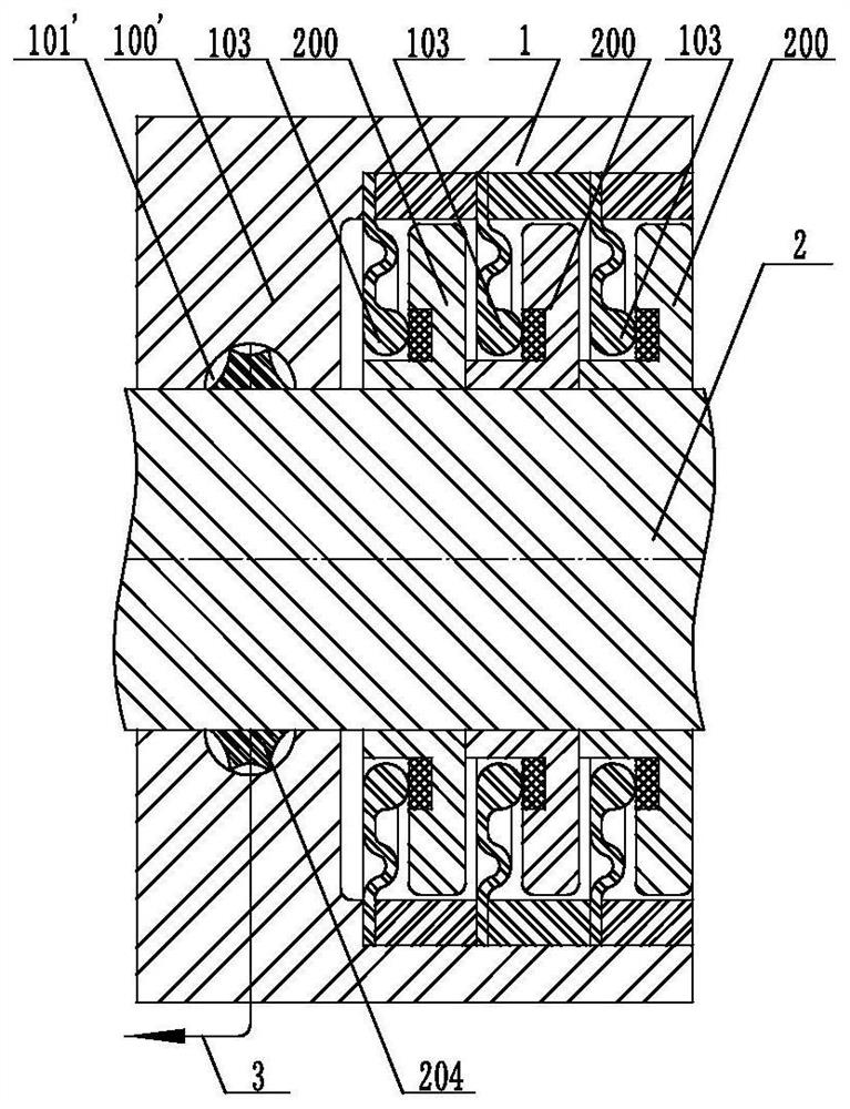
[0059] See attached figure 1 , suitable for low-speed rotation such as the sealing of valve stems. From left to right, the inner cavity of the sealing chamber 1 is the end plate 100' and the annular drainage groove 101', the first-stage annular spring clutch, the sealing ring seat A200, and the second-stage annular spring Disc clutch, seal ring seat A200, three-stage annular spring disc clutch, seal ring seat A200, a connecting pipe 3 runs through the inner cavity of the drainage groove 101', and the seal rings 103 of the ring spring disc clutches at all levels are connected to the corresponding seal ring seats The sealing end faces of A200 are closely attached, wherein, the three sealing ring seats A200 are all fixed on the rotating shaft 2, and at the same time, a diversion ring platform 204 is set on the rotating shaft 2 surrounded by the drainage groove 101'; when the container or pipeline fluid pressure The bigger the fit, the tighter the fit. When there is negative press...
Embodiment 2
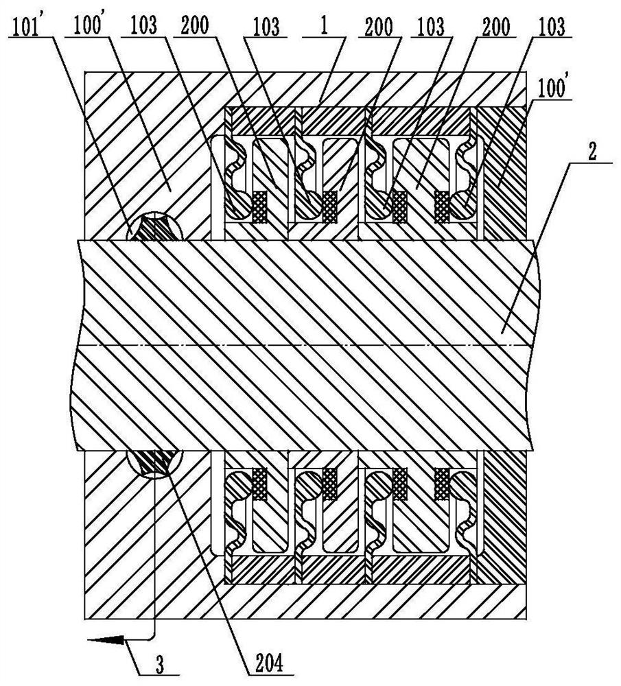
[0062] See attached figure 2 , suitable for low-speed rotation such as the sealing of valve stems. From left to right, the inner cavity of the sealing chamber 1 is the end plate 100' and the annular drainage groove 101', the first-stage annular spring clutch, the sealing ring seat A200, and the second-stage annular spring plate clutch, sealing ring seat A200, three-stage annular spring plate clutch, sealing ring seat A200, reversely arranged fourth-stage annular spring plate clutch, end plate 100′, and a communication pipe 3 running through the inner cavity of drainage groove 101′; Among them, the sealing ring 103 of the fourth-stage annular spring clutch arranged in reverse and the sealing end surface of the corresponding third sealing ring seat A200 constitute a sealing pair, and the sealing rings 103 of the annular spring clutches of each stage and the corresponding sealing ring The sealing end faces of the ring seat A200 are closely attached to each other; at the same tim...
Embodiment 3
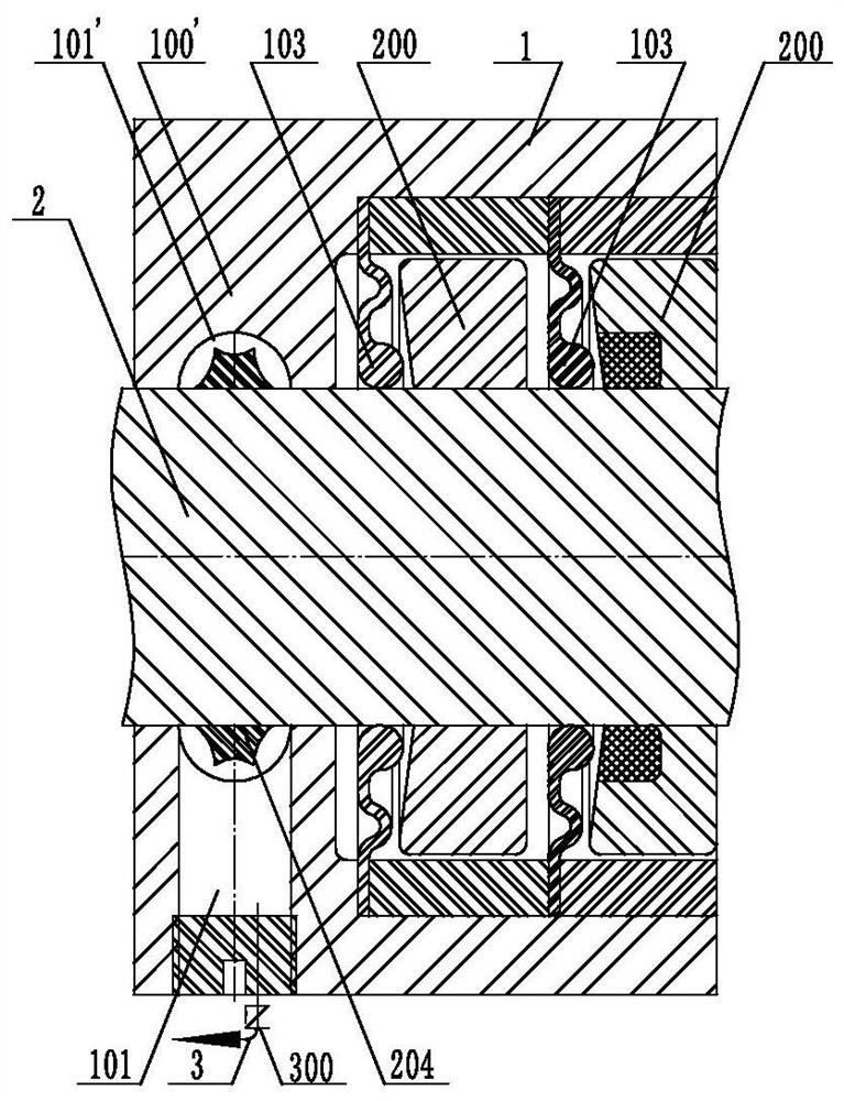
[0065] See attached image 3 , from left to right are the end plate 100' and the discharge well 101, the first-stage annular spring clutch, the seal ring seat A200, the second-stage annular spring clutch, and the seal ring seat A200. The corresponding sealing ring seat A200 is embedded with a flexible sealing ring, and a connecting pipe 3 with a check valve 300 is connected to the discharge well 101; the inner ring surface of the sealing cabin 1 above the discharge well 101 has a drainage groove 101' around the rotating shaft 2, and the drainage There is a guide ring platform 204 on the rotating shaft 2 surrounded by the groove 101'.
[0066] attached image 3 As shown, at this time, the fluid in the discharge well 101 is dredged through the connecting pipe 3, and the rotating shaft 2 is turned on to rotate. The seal ring 103 of the primary ring spring clutch is kept at a distance from the corresponding seal ring seat A200, and the seal ring 103 of the secondary ring spring c...
PUM
 Abstract
Description
Claims
Application Information
 - R&D Engineer
- R&D Manager
- IP Professional
- Industry Leading Data Capabilities
- Powerful AI technology
- Patent DNA Extraction
Browse by: Latest US Patents, China's latest patents, Technical Efficacy Thesaurus, Application Domain, Technology Topic, Popular Technical Reports.
© 2024 PatSnap. All rights reserved.Legal|Privacy policy|Modern Slavery Act Transparency Statement|Sitemap|About US| Contact US: help@patsnap.com