LEG type slipper bracket and manufacturing process thereof

A sliding shoe and supporting shoe technology, applied in the directions of bearings, shafts, coatings, etc., can solve the problems of unsatisfactory combination of alloy and matrix, difficult installation, high installation cost, cumbersome installation process, etc., so as to improve the efficiency of cold oil lubrication, combine Excellent performance, the effect of reducing the assembly cycle

Pending Publication Date: 2021-07-23
宜兴市环宇轴瓦制造有限公司
View PDF0 Cites 0 Cited by
  • Summary
  • Abstract
  • Description
  • Claims
  • Application Information

AI Technical Summary

Problems solved by technology

[0009] Finally, by adding a direct lubricating channel design to the new structure, the high-pressure oil circuit realizes that the shaft is lifted by high-pressure oil before the whole machine runs to avoid scratching the bearing alloy due to inert boundary lubrication due to low speed in the early start-up period, and the high-pressure is turned off after the whole machine starts and runs in balance The oil circuit and the low-pressure oil circuit are forced to supply oil, and always achieve a high-efficiency lubrication state, so as to solve the problems of unsatisfactory combination of the alloy and the substrate, cumbersome installation process, difficult installation, high installation cost, and poor lubricating performance

Method used


Image

  • LEG type slipper bracket and manufacturing process thereof
  • LEG type slipper bracket and manufacturing process thereof
  • LEG type slipper bracket and manufacturing process thereof

Examples


Embodiment Construction

[0038] The preferred embodiments of the present invention will be described below in conjunction with the accompanying drawings. It should be understood that the preferred embodiments described here are only used to illustrate and explain the present invention, and are not intended to limit the present invention.

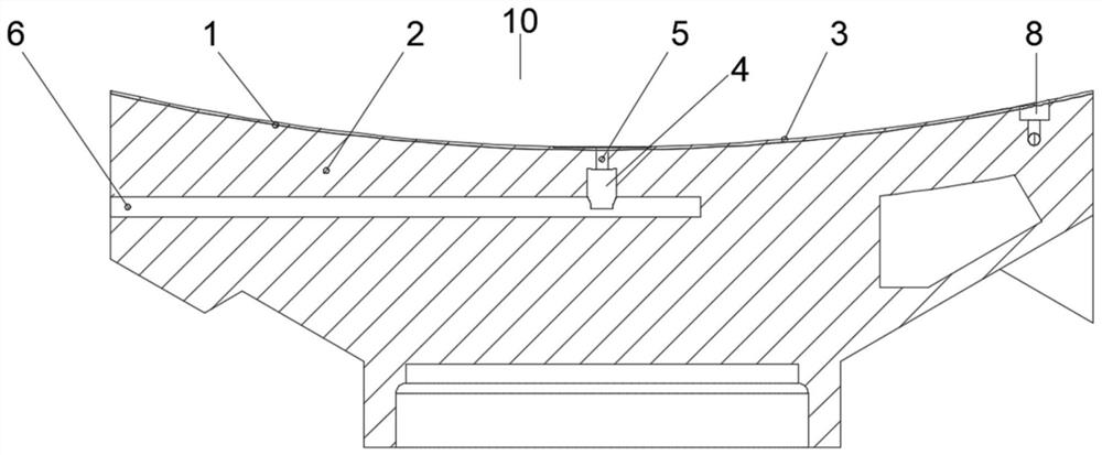
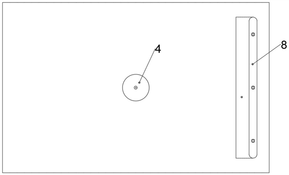
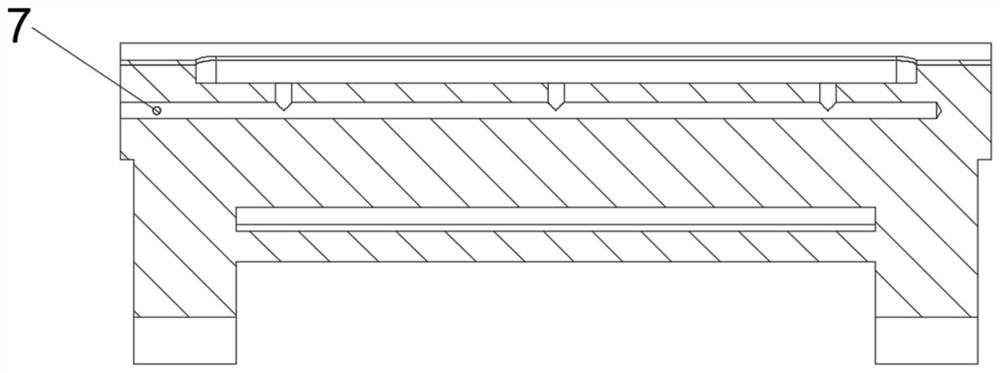
[0039] Refer to attached Figure 1-Figure 6 , a LEG type sliding shoe shoe and its manufacturing process provided by the present invention, including a sliding shoe shoe 10;

[0040] Further, the sliding shoe shoe 10 is composed of a tin-based Babbitt alloy layer 1 and a bearing base 2, and the tin-based Babbitt alloy layer 1 is clad on the bearing base 2 by arc deposition, and the tin-based Babbitt alloy layer 1 is clad on the bearing base 2 by arc deposition. The thickness of the babbitt alloy layer 1 is set to 3-4 mm, specifically, the thickness of the tin-based babbitt alloy layer 1 is preferably 3.5 mm.

[0041] Further, the inner wall of the top end of the be...


PUM

PropertyMeasurementUnit
Thicknessaaaaaaaaaa

Abstract

The invention discloses an LEG type slipper bracket and a manufacturing process thereof, and particularly relates to the technical field of slipper brackets. The technical scheme is that the LEG type slipper bracket comprises a slipper bracket, the slipper bracket is composed of a tin-based babbitt metal layer and a bearing base body, the tin-based babbitt metal layer is clad on the bearing base body through electric arc deposition, the thickness of the tin-based babbitt metal layer is set to be 3 to 4mm, and a slipper bracket inner hole is formed in the inner wall of the top end of the bearing base body. The inner wall of the top end in the middle of the bearing base body is provided with a high pressure oil jacking oil cavity. The LEG type slipper bracket has the beneficial effects that the bonding strength of traditional centrifugal casting is about 35 Mpa, the loaded deformation is reduced due to the thin alloy layer, the higher strength is obtained, the alloy hardness after welding is higher, wear resistance is higher, the power loss is reduced, a runner for direct lubricating oil feeding is designed for oil supply, insufficient lubricating oil feeding is avoided, the cold oil lubricating efficiency is improved, the lubricating performance of the slipper bracket is improved, and temperature rise is reduced.

Description

technical field [0001] The invention relates to the field of sliding shoe supports, in particular to a LEG type sliding shoe shoe and a manufacturing process thereof. Background technique [0002] The ball mill is the key equipment for crushing the material after being crushed. The sliding shoe shoe is an indispensable mechanical part of the crushing and grinding ball mill in mining, building materials, chemical industry, and metallurgical machinery. It plays an important supporting role for the entire large ball mill equipment. One of the most important stress-bearing parts in the entire ball mill, the performance of the sliding shoe shoe directly affects the service life and operating efficiency of the ball mill, and even affects the operation safety of the whole machine. The new generation of sliding shoe shoe adopts the direct lubrication technology LEG . [0003] There are following deficiencies in the prior art: Existing: 1. Most of the sliding shoe supports are lead-...

Claims


Application Information

Patent Timeline
IPC IPC(8): F16C32/06F16C33/12F16C33/14F16C37/00B02C17/18
CPCB02C17/181F16C32/064F16C32/0651F16C32/0655F16C32/0659F16C32/0674F16C32/0681F16C33/121F16C33/124F16C33/14F16C37/002F16C2204/34F16C2204/60F16C2220/60F16C2223/46F16C2226/36F16C2240/44F16C2240/54F16C2240/60F16C2320/23
Inventor 吴秋平沈俊赵林辉梅亮郭桢鲁玉龙
Owner 宜兴市环宇轴瓦制造有限公司
Why Eureka
Try Eureka