Vapor chamber

A technology of vapor chamber and capillary structure, which is applied in the direction of cooling/ventilation/heating transformation, electrical components, heat exchange equipment, etc., and can solve the problem of heat dissipation efficiency failure of the vapor chamber, accumulation in a narrow area or difficulty in passing through a narrow area and reflowing To the position where the vapor chamber is in thermal contact with the heat source, etc., to achieve the effect of improving the heat dissipation capacity

Pending Publication Date: 2021-07-09
VAST GLORY ELECTRONICS &HARDWARE &PLASTIC HUI ZHOU LTD
View PDF0 Cites 0 Cited by
  • Summary
  • Abstract
  • Description
  • Claims
  • Application Information

AI Technical Summary

Problems solved by technology

If the shape of the vapor chamber has a narrow area, then when the vapor chamber is operated against gravity (that is, the position where the vapor chamber contacts the heat source is located on the upper side of the vapor chamber), the working fluid will flow due to the narrow area. The cross-sectional area of ​​the capillary structure inside is small, so it accumulates in the narrow area or it is difficult to pass through the narrow area and return to the position where the vapor chamber is in thermal contact with the heat source, which causes the heat dissipation efficiency of the vapor chamber to fail.

Method used


Image

  • Vapor chamber
  • Vapor chamber
  • Vapor chamber

Examples


Embodiment Construction

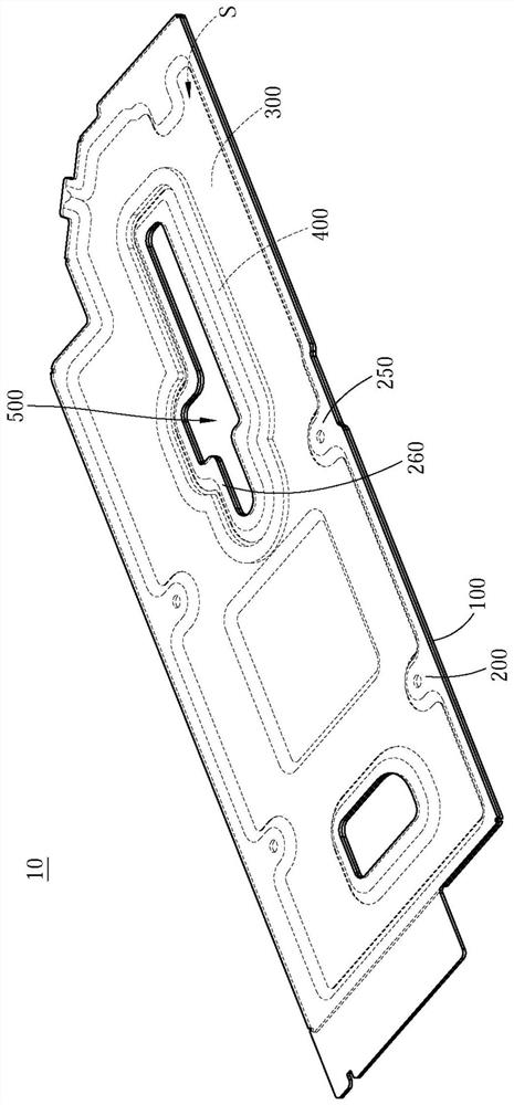
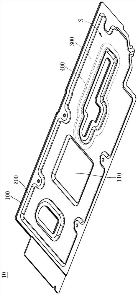
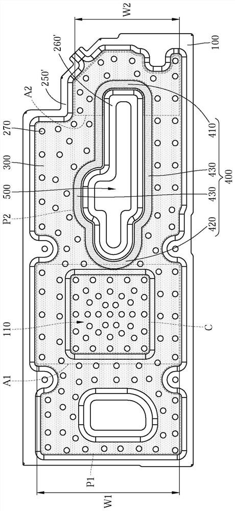
[0049] see Figure 1 to Figure 4 . figure 1 It is a perspective view of the temperature chamber according to the first embodiment of the present invention. figure 2 for figure 1 A perspective view of the vapor chamber of . image 3 for figure 1 Plan view of the vapor chamber with the second cover removed. Figure 4 for figure 1 sectional view.

[0050] The vapor chamber 10 of this embodiment is used for accommodating a cooling fluid (not shown in the figure). The vapor chamber 10 includes a first cover 100 , a second cover 200 , a first capillary structure 300 and a second capillary structure 400 .

[0051] The material of the first cover 100 and the second cover 200 is, for example, oxygen-free copper, silicon-containing alloy copper or phosphorus-containing alloy copper plate, and the second cover 200 and the first cover 100 are joined together to form a liquid-tight The space S, the liquid-tight space S is used to accommodate cooling fluid (not shown in the figure)...


PUM


Abstract

A vapor chamber is used for accommodating a cooling fluid. The vapor chamber comprises a first cover body, a second cover body, a first capillary structure and a second capillary structure. The second cover body and the first cover body are connected to form a liquid-tight space together, and the liquid-tight space is used for containing cooling fluid. The first capillary structure is located in the liquid-tight space and stacked on the first cover body. The second capillary structure is located in the liquid-tight space and stacked on the first capillary structure. The second capillary structure is different from the first capillary structure, and the projection of the second capillary structure on the first cover body is smaller than the projection of the first capillary structure on the first cover body.

Description

technical field [0001] The invention relates to a uniform temperature plate, in particular to a uniform temperature plate with a composite capillary structure. Background technique [0002] The technical principle of the vapor chamber is similar to that of a heat pipe, but there are differences in the way of conduction. The heat pipe is one-dimensional linear heat conduction, while the heat in the vapor chamber is conducted on a two-dimensional surface, so the efficiency is higher. Specifically, the vapor chamber mainly includes a cavity and a capillary structure. There is a hollow chamber inside the cavity, and the hollow chamber is used for filling with a working fluid. Capillary tissue is arranged in the hollow chamber. The heated part of the cavity is called the evaporation zone. The part of the cavity where heat is dissipated is called the condensation zone. The working fluid absorbs heat in the evaporation area and vaporizes and rapidly expands to the entire cavit...

Claims


Application Information

Patent Timeline
Patent Type & Authority Applications(China)
IPC IPC(8): H05K7/20
CPCH05K7/20336F28D15/0233F28D15/046F28F3/14F28F3/044H01L23/427
Inventor 刘垒垒张小敏王学梅
Owner VAST GLORY ELECTRONICS &HARDWARE &PLASTIC HUI ZHOU LTD
Why Eureka
Try Eureka