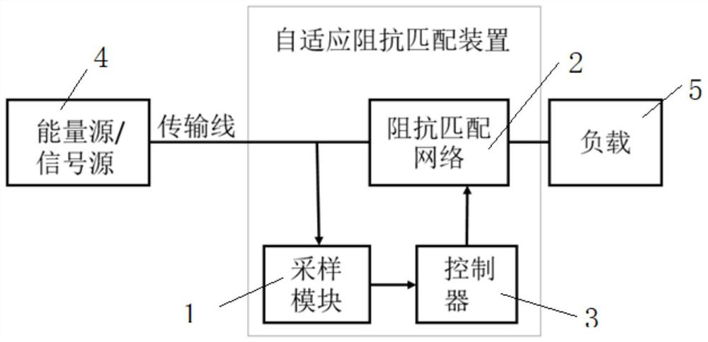
Impedance matching network, self-adaptive impedance matching device and self-adaptive impedance matching method
An impedance matching network and impedance matching technology, applied in the direction of impedance network, multi-terminal pair network, electrical components, etc., can solve the problems of slow response speed, difficult to apply load, small adjustment range, etc., achieve low cost, reduce sampling speed and Requirements for time accuracy and the effect of simple implementation
- Summary
- Abstract
- Description
- Claims
- Application Information
AI Technical Summary
Problems solved by technology
Method used
Image
Examples
Embodiment 1
[0068] like figure 2 A Γ-type impedance matching network is shown, which is composed of 6 capacitors and 6 inductors. Among them, the variable capacitor is composed of 5 capacitors C1~C5 connected in series, and the variable inductor is composed of 5 inductors L1~L5 connected in parallel. to make. Among them, C1-C5, L1-L5 are respectively connected with the corresponding relays, and the controller controls the relay group to realize the adjustable capacitance and inductance. In this embodiment, the capacitance value of the adjacent capacitor is reduced to 1 / 2 of the original capacitance value; the inductance value of the adjacent inductor is reduced to 1 / 2 of the original inductance value.
[0069] Therefore, the relative error of the varactor inductance is 1 / 2 6 =1.56%, in other embodiments, if the adjustment accuracy needs to be improved, the quantity of capacitors and inductors can be increased accordingly.
[0070] The access state of the relay group set corresponding ...
Embodiment 2
[0080] Based on the impedance matching network and the applied adaptive impedance matching device of Embodiment 1, this embodiment provides an impedance measurement method.
[0081] like image 3 One implementation of the sampling module is shown. It uses a dual directional coupler to measure the voltage amplitude of the incident and reflected waves, which is a widely used and inexpensive transmission line voltage measurement method; where, V + , V - The voltages at both ends correspond to the voltage amplitudes of the incident and reflected waves, respectively. Measurements can be made using a common ADC. Since there is a forward voltage drop when the diode is turned on, it is necessary to correct the voltage value collected by the ADC to obtain the actual voltage amplitude of the incident and reflected waves.
[0082] combine figure 2 Given the impedance matching network and image 3 Given the sampling module, this embodiment provides an optimized impedance measureme...
PUM
 Abstract
Description
Claims
Application Information
 - R&D
- Intellectual Property
- Life Sciences
- Materials
- Tech Scout
- Unparalleled Data Quality
- Higher Quality Content
- 60% Fewer Hallucinations
Browse by: Latest US Patents, China's latest patents, Technical Efficacy Thesaurus, Application Domain, Technology Topic, Popular Technical Reports.
© 2025 PatSnap. All rights reserved.Legal|Privacy policy|Modern Slavery Act Transparency Statement|Sitemap|About US| Contact US: help@patsnap.com


