
Uniform glue spraying equipment and process for MEMS chip

A chip and equipment technology, applied in the field of MEMS chip spraying and leveling equipment, can solve the problems of lack of MEMS manufacturing process in manufacturing technology, improvement of MEMS production efficiency, difficulty in realizing standardization, etc., and achieve linear working range and incremental control of glue amount. And stable uniformity, improve efficiency, break through the effect of high cost

Pending Publication Date: 2021-07-09
硅芯崟半导体设备科技(苏州)有限公司
View PDF0 Cites 1 Cited by
  • Summary
  • Abstract
  • Description
  • Claims
  • Application Information

AI Technical Summary

Problems solved by technology

MEMS processing is developed through the manufacture of integrated circuits. However, MEMS manufacturing involves the exchange of various materials. MEMS manufacturing technology is more personalized and diversified, and is widely used in various fields. This diversification of manufacturing processes gives The realization of standardization in its process has brought difficulties, and the current manufacturing technology lacks a standard MEMS manufacturing process
[0004] At present, the uniform glue development equipment in the manufacture of MEMS chips uses the same process as the integrated circuit chip manufacturing. The glue uniform development equipment used in integrated circuit chips is mainly the rotary glue technology. The rotary glue coating is only for flat surface topography, or The fluctuation of the surface structure is in the nanometer range, and the fluctuation of the surface topography of the MEMS chip reaches the level of microns or even millimeters. The thickness of the glue is required to be different in different regions. The pain points in MEMS research and development are also the pain points that limit the improvement of MEMS production efficiency

Method used


Image

  • Uniform glue spraying equipment and process for MEMS chip
  • Uniform glue spraying equipment and process for MEMS chip
  • Uniform glue spraying equipment and process for MEMS chip

Examples


Embodiment Construction

[0033] The following will clearly and completely describe the technical solutions in the embodiments of the present invention with reference to the accompanying drawings in the embodiments of the present invention. Obviously, the described embodiments are only some, not all, embodiments of the present invention. Based on the embodiments of the present invention, all other embodiments obtained by persons of ordinary skill in the art without making creative efforts belong to the protection scope of the present invention.

[0034] In the following description, many specific details are set forth in order to fully understand the present invention, but the present invention can also be implemented in other ways different from those described here, therefore, the protection scope of the present invention is not limited by the specific implementation disclosed below. Example limitations.

[0035] In describing the present invention, it should be understood that the terms "center", "l...


PUM


Abstract

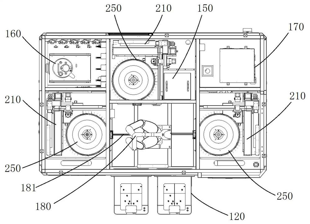
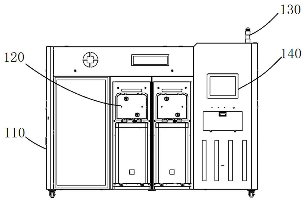
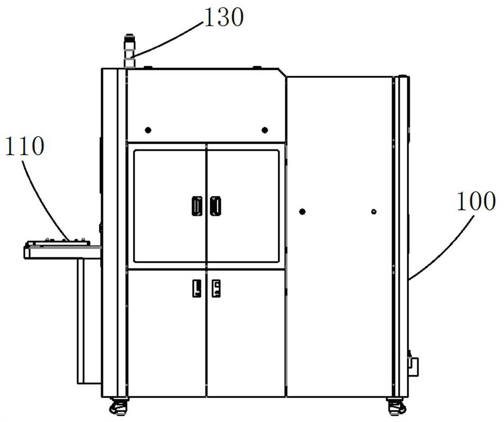
The invention discloses a uniform glue spraying equipment and process for an MEMS chip. The uniform glue spraying equipment comprises a gas supply mechanism and an electrical control mechanism which are arranged on an assembly box body, wherein a material taking and placing area is arranged in the assembly box body, a positioning track is arranged in the material taking and placing area, an intelligent mechanical arm is arranged on the positioning track and is used for taking and placing a wafer, a plurality of glue spraying stations are arranged in the circumferential direction of the material taking and placing area, and glue spraying modules are arranged at the glue spraying stations. Each glue spraying module comprises X-coordinate and Y-coordinate tracks arranged on a mounting base, wherein a glue spraying area is arranged on the mounting base, a wafer to be processed is placed on the glue spraying area, a heating soft fixing disc is arranged above the glue spraying area, a protection plate is arranged on one side of the heating soft fixing disc, a wafer inlet and outlet protection opening is formed in the protection plate, ultrasonic spray heads are arranged on the X-coordinate and Y-coordinate tracks, and spray nozzles are arranged below the ultrasonic spray heads. By utilizing the effective combination of the glue spraying modules and a heating mechanism, glue spraying efficiency is effectively improved, photoresist spraying precision is improved, excessive use of a photoresist is avoided, and the waste of the photoresist is reduced.

Description

technical field [0001] The invention relates to the technical field of chip processing, in particular to a MEMS chip glue spraying equipment and a process method thereof. Background technique [0002] At present, the lithography process in semiconductor wafer processing is completed by coating machine, lithography machine, and developing machine to complete the photoresist coating, lithography, and development operations on the wafer respectively. With the improvement of semiconductor wafer processing technology, technology The researchers proposed a device system that connects the gum coating and developing equipment with the photolithography machine to realize the entire photolithography process. This device system can improve the production efficiency of the photolithography process. Glue coating and development equipment is an indispensable processing equipment in the chip manufacturing process. It uses the robot to realize the transfer and processing of the wafer betwee...

Claims


Application Information

Patent Timeline
Patent Type & Authority Applications(China)
IPC IPC(8): G03F7/16B81B7/02
CPCG03F7/16G03F7/168B81B7/02
Inventor 朱瑞盈国亮
Owner 硅芯崟半导体设备科技(苏州)有限公司
Learn More