Special-shaped glass cutting machine for touch screen production

A touch screen and cutting machine technology, applied in stone processing tools, work accessories, manufacturing tools, etc., can solve the problems of touch screen lack of positioning measures, touch screen position offset, cutting precision reduction, etc., to achieve stable cutting, improve precision, and keep clean degree of effect

Pending Publication Date: 2021-07-09
湖北信永辉电子科技有限公司
View PDF9 Cites 3 Cited by
  • Summary
  • Abstract
  • Description
  • Claims
  • Application Information

AI Technical Summary

Problems solved by technology

However, when the cutting shape is special-shaped, it needs to be operated on a special-shaped cutting machine, but the existing special-shaped cutting machine lacks positioning measures for the touch screen. When cutting, the touch screen will have a position offset problem, resulting in a reduction in cutting accuracy; The debris generated or the dust and debris accumulated on the cutting machine also affect the cutting accuracy of the touch screen during cutting, so it is necessary to keep the cutting machine table clean

Method used


Image

  • Special-shaped glass cutting machine for touch screen production
  • Special-shaped glass cutting machine for touch screen production
  • Special-shaped glass cutting machine for touch screen production

Examples


Embodiment 1

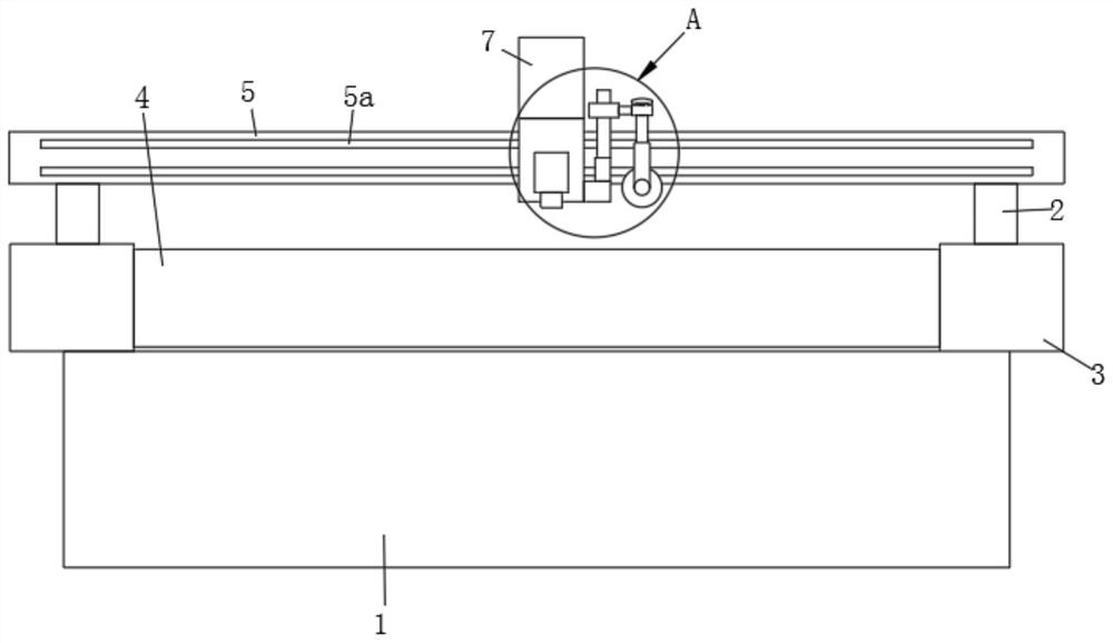
[0039] Such as figure 1 As shown, the present invention provides a special-shaped glass cutting machine for touch screen production, including a support base 1, a movable column 2, a fixed table 3, a transmission platform 4, a traverse seat 5, a cutting seat 7, and a positioning assembly 8.

[0040]A transmission platform 4 is installed on the top of the support base 1 . The transmission platform 4 is fixed with fixed tables 3 symmetrically on both sides along the conveying direction. A movable column 2 sliding along the length direction of the fixed platform 3 is installed on the two fixed platforms 3 . A traversing seat 5 is fixed between the tops of the two movable columns 2 by bolts. A guide rail bar 5a is fixed on the facade of the traversing seat 5 by bolts. The guiding of the guide rail bar 5 a is parallel to the longitudinal direction of the traversing seat 5 .

[0041] The cutting seat 7 is installed on the rail bar 5a. And the cutting seat 7 moves along the guid...

Embodiment 2

[0046] Such as image 3 and Figure 4 As shown, the air blowing assembly 9 includes a main pipe 901 , a connecting block 902 , an air nozzle 903 and a branch pipe 904 . A main pipe 901 is fixed on one end of the traversing base 5 through a connecting block 902 . The manifold 901 communicates with a positive pressure air source. A branch pipe 904 is led out from the main pipe 901 . The end of the branch pipe 904 is clamped with a gas nozzle 903 whose gas flow direction faces the surface of the transmission platform 4 .

[0047] The connecting block 902 is fixed on the end face of the traversing base 5 by bolts. It is convenient to disassemble the connection block 902 and the connected main pipe 901.

[0048] The gas nozzle 903 adopts a porous nozzle structure. Expand the impact range of the airflow and improve the blowing effect.

[0049] When the traversing seat 5 moves, the main pipe 901 moves with the traversing seat, and when the cutting knife 7a cuts and generates d...

Embodiment 3

[0051] Such as Figure 5 and Figure 6 As shown, on the basis of the second embodiment, the other end of the traversing seat 5 is also provided with a cleaning assembly 6 . The cleaning assembly 6 includes a cleaning guide rail 601 , a cleaning guide sleeve 602 , a cleaning cylinder 603 , a cleaning brush 604 and a cleaning bracket 605 . A cleaning bracket 605 is fixed on the fixed platform 3 close to the other end of the traversing seat 5 by bolts. The top end of the cleaning bracket 605 is fixed with a cleaning guide rail 601 arranged above the edge of the transmission platform 4 by bolts. The guiding of the cleaning guide rail 601 is parallel to the conveying direction of the transmission platform 4 . The cleaning guide rail 601 is covered with a cleaning guide sleeve 602 guiding and sliding along the cleaning guide rail 601 . A sweeping brush is installed on the bottom of the cleaning guide sleeve 602 .

[0052] Specifically, the bottom of the cleaning guide sleeve 60...


PUM


Abstract

The invention relates to the technical field of touch screen production, and provides a special-shaped glass cutting machine for touch screen production. The cutting machine comprises a supporting base, movable columns, fixing tables, a transmission platform, a transverse moving seat, a cutting seat and a positioning assembly, wherein the transmission platform is mounted at the top of the supporting base, the fixing tables are symmetrically fixed to the two sides, in the conveying direction, of the transmission platform, the movable columns sliding in the length direction of the fixing tables are mounted on the two fixed tables, the transverse moving seat is fixed between the top ends of the two movable columns, a guide rail strip is fixed on the vertical surface of the transverse moving seat, the cutting seat is mounted on the guide rail strip, the cutting seat moves along the guide of the guide rail strip, a cutting knife is fixed on one side of the cutting seat, the positioning assembly is fixedly mounted on one side of the cutting seat, and the positioning end of the positioning assembly is pressed on the screen surface of a touch screen on the transmission platform. According to the cutting machine, the positioning assembly is arranged to position the touch screen on the transmission platform, then the cutting knife cuts the touch screen, cutting is stable, and it is guaranteed that the touch screen cannot move in the cutting process.

Description

technical field [0001] The invention relates to the technical field of touch screen production, in particular to a special-shaped glass cutting machine for touch screen production. Background technique [0002] The touch screen needs to be cut during the production process. For example, the patent document with the application number CN201922124554.3 discloses a glass cutting machine with a touch screen, including a limit rod, a horizontal slider, forward and reverse buttons, an electric telescopic rod, a linear Motor, motor, bevel gear, transmission rod and helical gear, the horizontal slider is installed in the middle of the slider, the rear side of the horizontal slider is equipped with a limit rod, the front end of the horizontal slider is equipped with a forward and reverse button, and the inside of the horizontal slider A linear motor is installed, a motor is installed on the lower side of the horizontal slider, a helical gear is installed on the left side of the motor...

Claims


Application Information

Patent Timeline
IPC IPC(8): B28D1/22B28D7/02B28D7/04
CPCB28D1/22B28D7/02B28D7/04
Inventor 石辉陈航
Owner 湖北信永辉电子科技有限公司
Why Eureka
Try Eureka