
Cloth cutting device

A technology of cutting device and pressing device, which is applied in the cutting of textile materials, textiles and papermaking, etc. It can solve the problems of fabric slack, different elasticity of fabrics, and increased labor costs, so as to reduce the degree of deformation of fabrics and smooth winding Wrinkle-free and life-enhancing effects

Active Publication Date: 2017-09-08
杭州世佳布艺有限公司
View PDF6 Cites 19 Cited by
  • Summary
  • Abstract
  • Description
  • Claims
  • Application Information

AI Technical Summary

Problems solved by technology

[0004] In the textile industry, cloth slitting equipment is often used to divide the raw edge of the cloth or the cloth into small sections of equal or different lengths according to customer requirements for winding and packaging. However, the structure of the current slitting machine is unreasonable and requires multiple Workers manually press the cutter to divide, which increases the labor cost of the enterprise. The fabric has a certain degree of flexibility. Once the tension applied to the fabric changes during the cutting process, the fabric will produce different deformations, resulting in the final cut. The size accuracy of the fabric is low. The traditional take-up device is generally fixed to transport the fabric directly from the feed roller to the take-up rod. However, the elasticity of many fabrics is not the same. The fixed take-up method is adopted. It is easy to cause the fabric to slack during coiling, resulting in loose coiled fabric after coiling, which is not conducive to storage and affects product quality. Therefore, a fabric cutting device is proposed

Method used


Image

  • Cloth cutting device
  • Cloth cutting device
  • Cloth cutting device

Examples


Embodiment Construction

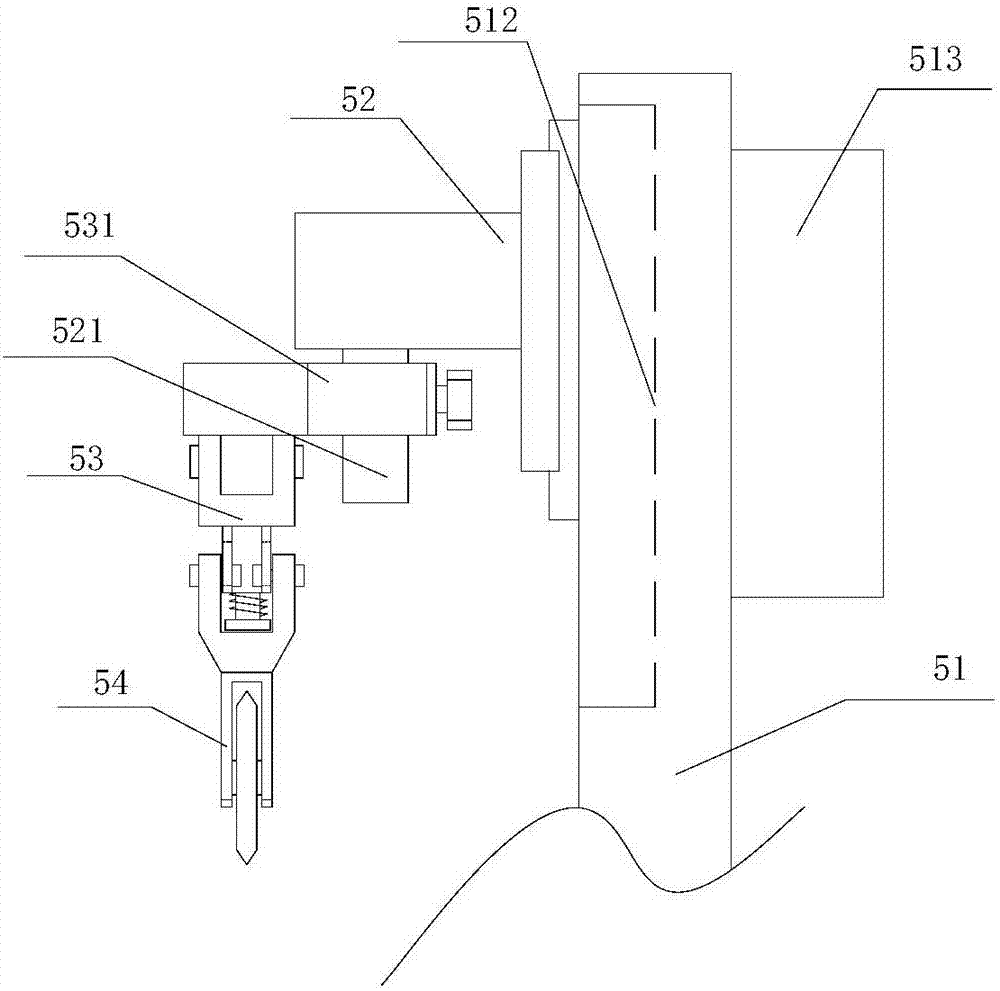
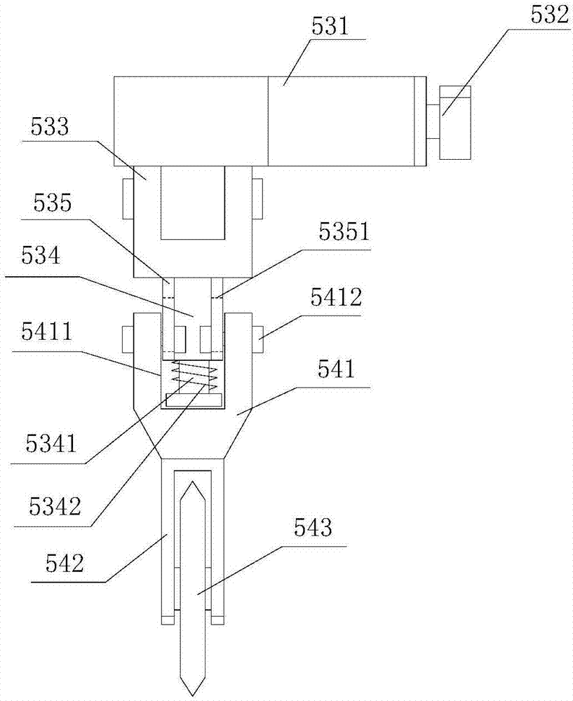
[0022] refer to Figure 1 to Figure 5 A fabric cutting device of the present invention includes a conveying roller device 1, an adjustable guide roller mechanism 2, an auxiliary roller assembly 3, a pressing device 4, a cutting device 5 and a winding device 6, and the two adjustable guide roller mechanisms 2 An adjustment device 21 is provided on the side, and a guide roller assembly 22 is installed between the adjustment devices 21. A knife seat 41 is provided on the pressing device 4, and a pressing mechanism 43 is provided on both sides of the knife seat 41. A cutting device 5 is provided above the pressing device 4, and auxiliary roller assemblies 3 are provided on both sides of the cutting device 5, and a mounting frame 51 is provided on the cutting device 5, and a vertical Sliding seat 512, horizontal sliding seat 52 is installed on the described vertical sliding seat 512, driving power box 513 is installed on the side wall of described installation frame 51, described d...


PUM


Abstract

The invention provides a cloth cutting device comprising a transport roller device, an adjustable guide roller mechanism, an auxiliary roller assembly, a press unit, a cutter and a rolling device; the press unit is provided with a tool rest; two sides of the tool rest are provided with a press mechanism; the cutter is arranged above the press unit; two sides of the cutter are provided with the auxiliary roller assembly; the cutter is provided with a vertical slide seat; a transverse slide seat is arranged on the vertical slide seat; one side of the transverse slide seat is provided with a buffer mounting rack; a cutter assembly is arranged below the buffer mounting rack; the cloth on the transport roller device passes the guide roller assembly, the auxiliary roller assembly, the press unit and the rolling device in sequence along the transport direction; the press unit can press tight the cloth on two sides of the tool rest, thus maximumly reducing the cloth deformation level, and ensuring the cutting process to be stable; the cutter assembly is provided with the buffer mounting rack, thus reducing bumps between the cutter and the tool rest in a cutting process, and reducing the cutter wearing.

Description

[0001] 【Technical field】 [0002] The invention relates to the technical field of cloth production, in particular to a cloth cutting device. [0003] 【Background technique】 [0004] In the textile industry, cloth slitting equipment is often used to divide the raw edge of the cloth or the cloth into small sections of equal or different lengths according to customer requirements for winding and packaging. However, the structure of the current slitting machine is unreasonable and requires multiple Workers manually press the cutter to divide, which increases the labor cost of the enterprise. The fabric has a certain degree of flexibility. Once the tension applied to the fabric changes during the cutting process, the fabric will produce different deformations, resulting in the final cut. The size accuracy of the fabric is low. The traditional take-up device is generally fixed to transport the fabric directly from the feed roller to the take-up rod. However, the elasticity of many fa...

Claims


Application Information

Patent Timeline
IPC IPC(8): D06H7/00
CPCD06H7/00
Inventor 王建兵
Owner 杭州世佳布艺有限公司
Learn More