Optical network service fault recovery method and system
A business failure and optical network technology, applied in the field of optical communication, can solve problems such as the availability of calculation results and the contradiction between calculation efficiency, and achieve the effects of eliminating resource allocation conflicts, improving calculation efficiency, and efficient and reliable recovery
- Summary
- Abstract
- Description
- Claims
- Application Information
AI Technical Summary
Problems solved by technology
Method used
Image

Examples
Embodiment 1
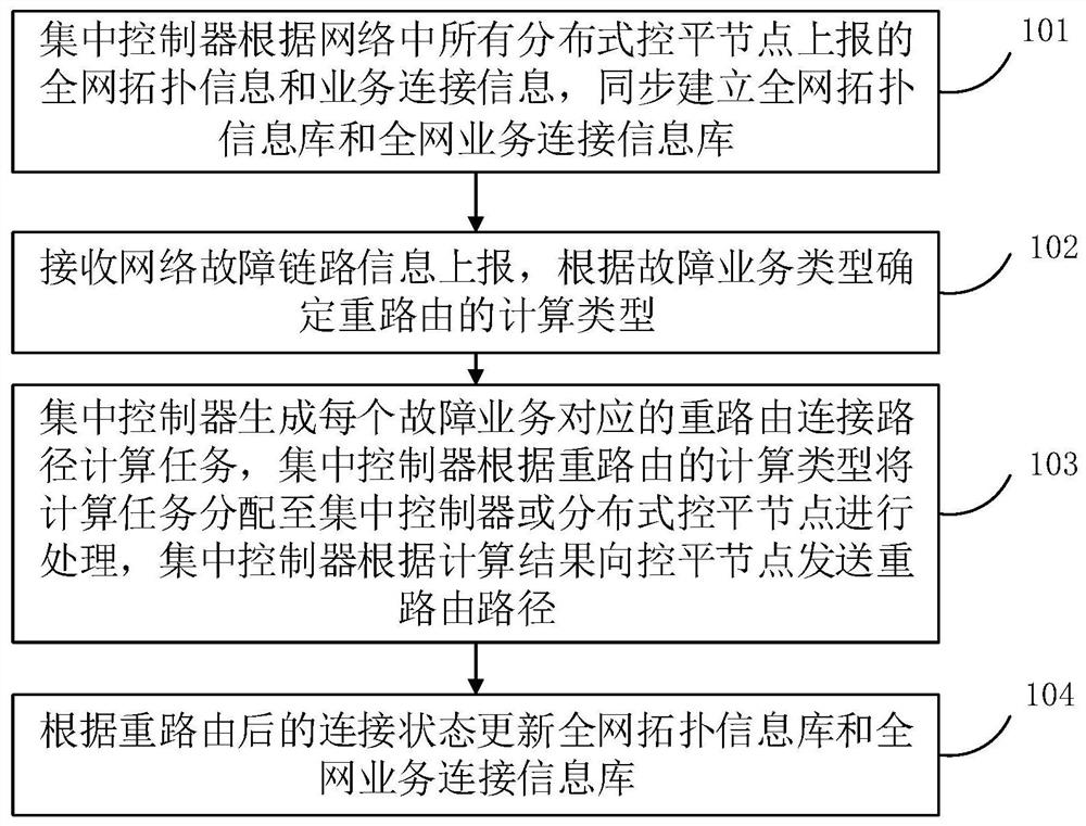
[0034] In the process of optical communication, in order to reduce the impact of network link or network node failure on the business, the optical network intelligent control system supports the automatic establishment of the end-to-end path of the business and the automatic recovery of the rerouting of the faulty connection. According to the transmission network topology automatic discovery protocol ITU-T G.7714.1, the optical network control system can automatically discover links, and establish a network-wide topology information database (Traffic Engineer Database, abbreviated as TE) based on Traffic Engineer (abbreviated as: TE) for TED). When the control system receives an end-to-end service connection establishment request, or receives a fault alarm that triggers the end-to-end rerouting recovery of the service connection, the control system will calculate the end-to-end connection path based on the entire network topology information database, and allocate transmission ...
Embodiment 2
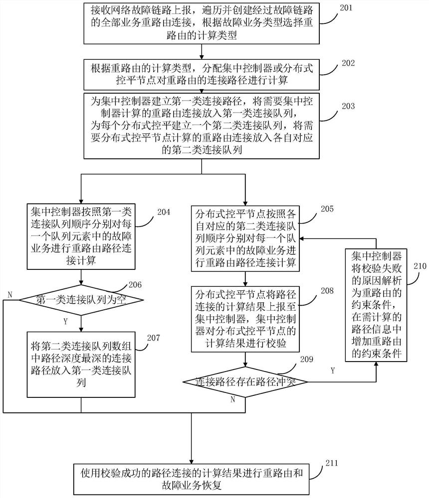
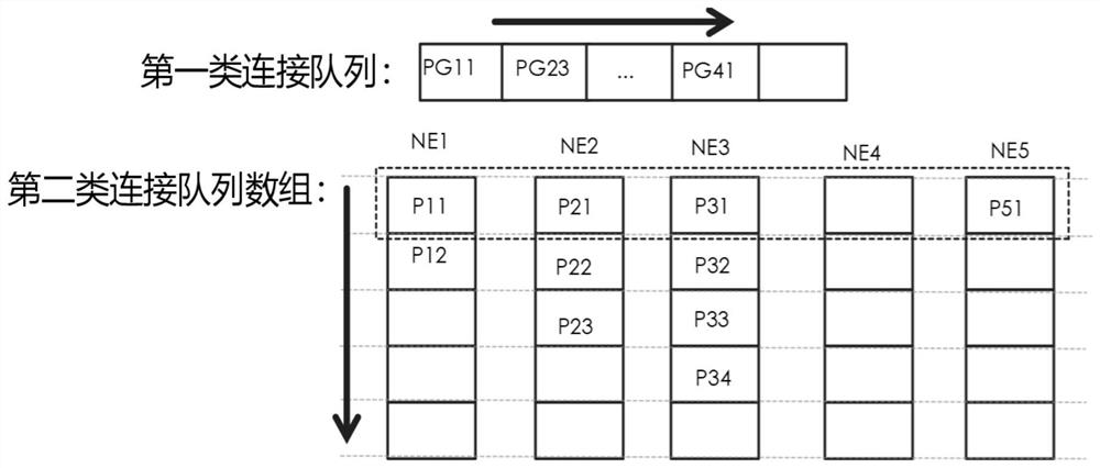
[0089] Based on the method for recovering optical network service failures provided in Embodiment 1, in a specific implementation scenario, specific applications can be implemented through the following procedures to control the rerouting connection recovery of multiple failed services.
[0090] Such as Figure 5 As shown in , it is a network topology diagram when the network link used in this embodiment does not fail. The network topology diagram includes five Reconfigurable Optical Add-Drop Multiplexer (Reconfigurable Optical Add-Drop Multiplexer, abbreviated as: ROADM) nodes NE1-NE5, and eight links (the two numbers in the link label of this embodiment respectively represent the chain node numbers at both ends of the path) and five service LSP1-LSP5 with rerouting protection recovery type. Among them, the name of each service connection includes the routing node number and occupied optical channel, such as LSP4 (1-2-5, CH3), indicating that the service connection sequence ...
Embodiment 3
[0102]On the basis of the methods for recovering optical network service failures provided in Embodiment 1 and Embodiment 2, this embodiment further provides a system for recovering optical network service failures. It includes a centralized controller subsystem 1 and at least one distributed level control node subsystem 2, and the centralized controller subsystem 1 and each distributed level control node subsystem 2 perform message interaction through the PCEP interface. Among them, the centralized controller subsystem 1 is a PCEP server, and each distributed control leveling node subsystem 2 is a PCEP client, which jointly completes the correspondence between the centralized controller and the distributed leveling node in Embodiment 1 and Embodiment 2. The optical network service fault recovery function.
[0103] Such as Figure 7 Shown is the system structure diagram provided by this embodiment.
[0104] The centralized controller subsystem 1 mainly completes the function...
PUM
 Abstract
Description
Claims
Application Information
 - R&D
- Intellectual Property
- Life Sciences
- Materials
- Tech Scout
- Unparalleled Data Quality
- Higher Quality Content
- 60% Fewer Hallucinations
Browse by: Latest US Patents, China's latest patents, Technical Efficacy Thesaurus, Application Domain, Technology Topic, Popular Technical Reports.
© 2025 PatSnap. All rights reserved.Legal|Privacy policy|Modern Slavery Act Transparency Statement|Sitemap|About US| Contact US: help@patsnap.com