A catheter system integrating ultrasound imaging and laser ablation

An ultrasound imaging and ablation technique, which is used in the field of intravascular imaging and vascular stenosis treatment, and can solve the problems of dissection or perforation, and the inability to determine the distal end of the ablation catheter.

Active Publication Date: 2022-05-20
HARBIN MEDICAL UNIVERSITY +1
View PDF10 Cites 0 Cited by
  • Summary
  • Abstract
  • Description
  • Claims
  • Application Information

AI Technical Summary

Problems solved by technology

[0003] However, excimer laser ablation still has certain risks
For example, if the distal end of the ablation catheter is healthy vascular tissue, the pulsed laser may ablate the healthy tissue, causing surgical events such as dissection or perforation
Also, in the absence of guidance from imaging techniques, physicians may not be able to determine whether the distal end of the ablation catheter is in full contact with the lesion

Method used


Image

  • A catheter system integrating ultrasound imaging and laser ablation
  • A catheter system integrating ultrasound imaging and laser ablation
  • A catheter system integrating ultrasound imaging and laser ablation

Examples


Embodiment 1

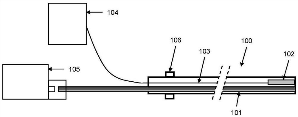
[0050] figure 1 A schematic diagram of a catheter system integrating ultrasound imaging and laser ablation is shown. The catheter system is in the form of a catheter 100 to facilitate access to the patient's blood vessels. The left end of the catheter 100 is called the proximal end of the catheter, and the right end of the catheter 100 is called the distal end of the catheter 200. The system contains an optical waveguide 101, an ultrasound imaging probe 102 and an ultrasound Signal channel 103. The proximal end of the optical waveguide 101 is connected to the pulsed laser light source 105 , and the distal end of the optical waveguide 101 terminates at the end face of the distal end 200 of the catheter. The proximal end of the ultrasonic signal channel 103 is connected to the ultrasonic imaging engine 104, the excitation signal sent from the ultrasonic imaging engine 104 is transmitted to the ultrasonic imaging probe 102 through the ultrasonic signal channel 103, and the elect...

Embodiment 2

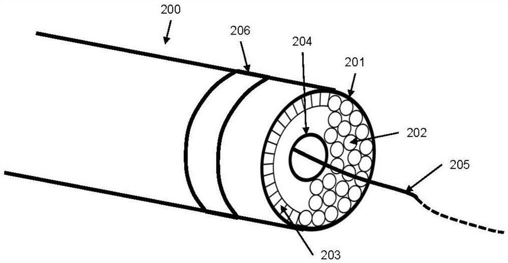
[0056] Figure 4 A schematic diagram of the distal end of the catheter of a catheter system integrating ultrasound imaging and laser ablation is shown. Different from the preferred embodiment 1, the array elements 203 are arranged in a ring along the pipe wall 404 of the catheter. The guide wire channel 204 remains in the middle of the catheter 100 . And the optical waveguide 101 , such as but not limited to the optical fiber 202 , is closely arranged between the ultrasonic sensor array 301 and the guide wire channel 204 . The ultrasound sensor and optical fiber 202 are designed to image the entire cross-section of the vessel wall, and the optical fibers 202 are also arranged concentric with the longitudinal axis of the catheter 100 . Such a design eliminates the need to re-rotate the proximal end of the catheter to image different quadrants of the vessel wall or perform ablation. However, the disadvantage of this is that the exit end face of the optical fiber 202 is far aw...

Embodiment 3

[0058] Figure 5 A schematic diagram of the distal end of the catheter of another catheter system integrating ultrasound imaging and laser ablation is shown. Similar to the preferred embodiment 2, the guide wire channel 204 remains in the middle of the catheter 100 . The difference is that, in the design of this preferred embodiment, the array elements 203 are arranged in a ring along the outer wall of the guide wire channel 204 . The optical fibers 202 are closely arranged between the ultrasonic sensor array 301 and the catheter wall 404 . This design can make the end face of the optical fiber 202 as close to the blood vessel wall as possible, so as to ablate the stenotic tissue close to the blood vessel wall. Since the ultrasonic sensor array 301 is far away from the vessel wall, when controlling the ultrasonic beam, the elevation angle of the scanning surface may need to be changed, such as but not limited to 45° or 50°. Another limitation of this design is that the spac...


PUM


Abstract

The invention provides a catheter system integrating ultrasonic imaging and laser ablation, comprising a catheter, the left and right ends of the catheter are the proximal end of the catheter and the distal end of the catheter respectively, the inner cavity of the catheter is provided with an optical waveguide and an ultrasonic signal channel, and the optical waveguide The proximal end of the waveguide is connected with a pulsed laser light source, and the distal end of the optical waveguide is terminated at the distal end face of the catheter. The laser pulses emitted by the pulsed laser light source are emitted from the front of the distal end of the catheter through the optical waveguide, and ablate the tissue in front of the catheter; the ultrasonic signal The proximal end of the channel is connected with an ultrasonic imaging engine, and the far end of the ultrasonic signal channel is connected with an ultrasonic imaging probe for forward-looking imaging. The ultrasonic imaging probe is used for focusing and scanning imaging to assist laser ablation. The present invention combines vascular ultrasonic imaging and laser ablation into a catheter system, which not only retains the therapeutic effect of laser ablation, but also provides image guidance for vascular ultrasonic imaging, and can improve the effectiveness of laser ablation in eccentric vascular stenosis. in the application.

Description

technical field [0001] The invention belongs to the technical field of intravascular imaging and vascular stenosis treatment, in particular to a catheter system integrating ultrasonic imaging and laser ablation. Background technique [0002] Skin coronary intervention (PCI) surgery usually sends a guide catheter to the coronary ostium to be dilated, and then sends a balloon of the corresponding size along the guide wire to the stenotic segment. It is performed with appropriate pressure and time according to the characteristics of the lesion To dilate to relieve arterial stenosis, traditional treatment methods include angioplasty and stent implantation. Plaque ablation is a cardiac interventional adjuvant therapy technique, including coronary atherectomy, orbital atherectomy, and laser ablation. In recent years, excimer laser (Excimer Laser) intracoronary plaque ablation has used ultraviolet light source, catheter design, and pulsed emission of cold light source to improve t...

Claims


Application Information

Patent Timeline
Patent Type & Authority Patents(China)
IPC IPC(8): A61B18/24A61B8/08
CPCA61B18/24A61B18/245A61B8/0891A61B8/42A61B2018/2255
Inventor 于波贾海波赵晨
Owner HARBIN MEDICAL UNIVERSITY
Why Eureka
Try Eureka