An automatic temperature control device for the production of nitrile non-slip gloves
An automatic temperature control and glove technology, applied in the direction of spraying device, device for coating liquid on the surface, pretreatment surface, etc., can solve the problems of poor product quality, affecting the gluing environment, and the problem of glove needle holes, so as to improve the gluing Uniformity, avoiding excessive temperature differences, and promoting the effect of gluing
- Summary
- Abstract
- Description
- Claims
- Application Information
AI Technical Summary
Problems solved by technology
Method used
Image
Examples
Embodiment 1
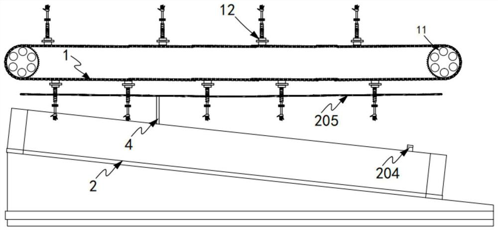
[0079] Such as figure 1 Shown, a kind of automatic temperature control device for the production of nitrile non-slip gloves, comprising:
[0080] A glove transmission mechanism 1, the glove transmission mechanism 1 includes a transmission unit 11, several groups of glove modules 12 arranged at equal intervals on the transmission unit 11, and a guide assembly for driving the glove modules 12 to carry out lifting work 13;
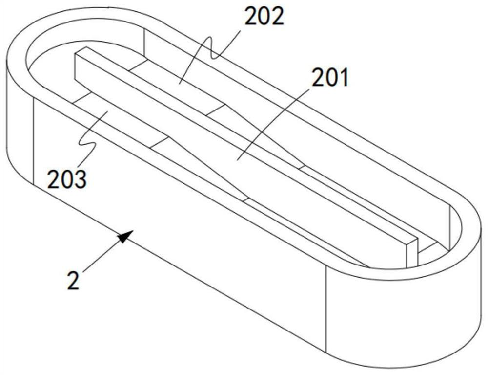
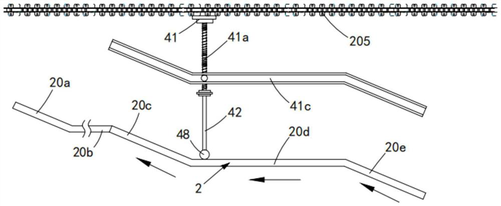
[0081] The dipping tank body 2, the dipping tank body 2 is arranged obliquely downward and is located below the transmission unit 11, the dipping tank body 2 is arranged in an elliptical structure, along the A partition plate 201 arranged in the middle of the body 2 and along the length direction of the dipping tank body 2 , a gluing space 202 and an impurity discharge space 203 are formed between the dipping tank body 2 and the partition plate 201 , the dipping tank body 2 is smoothly transitioned and connected by the first inclined part 20a, the first hor...
Embodiment 2
[0129] Such as Figure 9 to Figure 13 As shown, the components that are the same as or corresponding to those in the first embodiment are marked with the corresponding reference numerals in the first embodiment. For the sake of simplicity, only the differences from the first embodiment will be described below. The difference between this embodiment two and embodiment one is:
[0130] further, such as Figure 9 to Figure 13 Shown, described cleaning mechanism 4 comprises:
[0131] a base a41, the base a41 is arranged on any chain link of the chain mechanism 205;
[0132] The telescopic shaft 41a, the telescopic shaft 41a is arranged on the base a41 along the vertical direction and the lower end of the telescopic shaft 41a is provided with a base 41b, and the telescopic shaft 41a is completed under the action of the limit track 41c along the vertical direction. lifting work;
[0133] Rotating rod 42, the rotating rod 42 is rotated through the ring 43 and set in the guide gro...
PUM
 Abstract
Description
Claims
Application Information
 - R&D
- Intellectual Property
- Life Sciences
- Materials
- Tech Scout
- Unparalleled Data Quality
- Higher Quality Content
- 60% Fewer Hallucinations
Browse by: Latest US Patents, China's latest patents, Technical Efficacy Thesaurus, Application Domain, Technology Topic, Popular Technical Reports.
© 2025 PatSnap. All rights reserved.Legal|Privacy policy|Modern Slavery Act Transparency Statement|Sitemap|About US| Contact US: help@patsnap.com


