A multi-stage circulating jet spraying device for a packing-free cooling tower

A technology of spraying device and cooling device, applied in the field of cooling tower, can solve the problems of low efficiency, water vapor loss, waste, etc., and achieve the effect of good effect, reduced loss and good heat exchange effect

Active Publication Date: 2022-06-07
HUZHOU ZHONGYING ENERGY SAVING TECH
View PDF0 Cites 0 Cited by
  • Summary
  • Abstract
  • Description
  • Claims
  • Application Information

AI Technical Summary

Problems solved by technology

[0004] In view of the deficiencies in the prior art, the purpose of the present invention is to provide a multi-stage circulating jet spray device for a non-filler cooling tower, which solves the problems of low heat exchange efficiency and waste caused by a large amount of water vapor loss

Method used


Image

  • A multi-stage circulating jet spraying device for a packing-free cooling tower
  • A multi-stage circulating jet spraying device for a packing-free cooling tower
  • A multi-stage circulating jet spraying device for a packing-free cooling tower

Examples


Embodiment 1

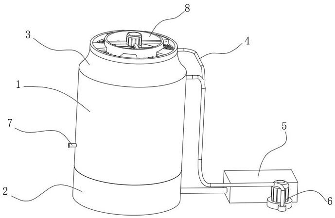
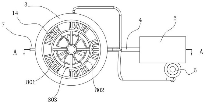
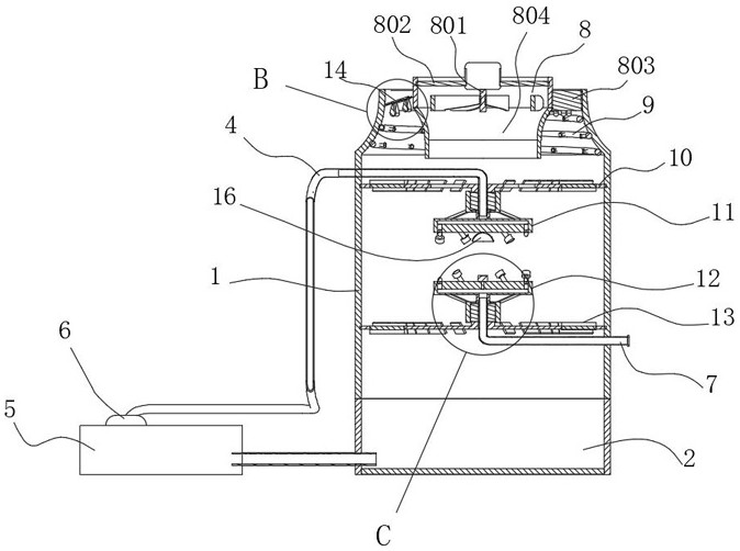
[0030] See Figure 1-8

[0031] In the present embodiment, the use of multi-stage cooling greatly improves the efficiency of heat exchange, and the multi-level water vapor recovery device can reduce the loss of water vapor, avoid waste, and water can be recycled to achieve high heat dissipation efficiency and less water vapor loss.

Embodiment 2

[0033] as Figure 1-8 As shown, on the basis of Example I, the present invention provides a technical solution: the secondary cooling device 9 is a spiral-shaped catheter, the outer wall of the secondary cooling device 9 is evenly distributed with several sprinkler heads 901.

[0034] In the present embodiment, the hot air mixed with water vapor inside the cooling tank 1 by the setting will rise along the inner wall of the cooling tank 1, when reaching the interior of the recovery cylinder 3, the spray head 901 outside the secondary cooling device 9 is sprayed out cold water to cool down again, and the spiral-shaped secondary cooling device 9 can be cooled at multiple levels, so that the cooling effect is better, the heat exchange is more complete, and most of the water vapor can be condensed into droplets after cold, reducing the loss of water vapor.

Embodiment 3

[0036] as Figure 1-8 As shown, on the basis of Example I, Example II, the present invention provides a technical solution: each steam recovery device 14 is tilted upwards from one end of the recovery cylinder 3, the bottom of each steam recovery device 14 is fixedly connected to at least one condensation block 1401, the condensation block 1401 is a small and large water droplet shape.

[0037] In the present embodiment, by the vapor recovery device 14 is provided, the condensed block 1401 at the bottom of the steam recovery device 14 due to the use of a streamlined water droplet state, the water vapor will move along the curved surface of the agglomeration block 1401, and finally crash into the steam recovery device 14, the water vapor condenses after liquefaction exothermic, the hot gas is blown out along the top of the recovery cylinder 3, and the liquefaction water flows into the interior of the cooling tank 1 along the slope of the steam recovery device 14, further to reduce t...


PUM


Abstract

The invention discloses a multi-stage circulating jet spray device for a filler-free cooling tower, which comprises a cooling tank, a recovery cylinder is fixedly connected to the top of the cooling tank, a water pool is fixedly connected to the bottom of the cooling tank, and The bottom of the inner wall is fixedly connected with a lower partition, the top of the lower partition is fixedly connected with a lower hot water nozzle, an upper cooling device is arranged above the lower hot water nozzle, and the top of the upper cooling device is fixedly connected with a The upper partition, the outer wall of the upper partition is fixedly connected with the inner wall of the cooling tank, and the interior of the recovery cylinder is provided with a fan duct. By adopting multi-stage cooling, the efficiency of heat exchange is greatly improved, and the multi-level water vapor The recovery device can reduce the loss of water vapor and avoid waste, and the water can be recycled to achieve high heat dissipation efficiency and less water vapor loss.

Description

Technical field [0001] The present invention belongs to the field of cooling tower technology, specifically relates to a multi-stage circulating jet spray device for a non-packing type cooling tower. Background [0002] A cooling tower is a device that uses water as a circulating coolant to absorb heat from a system and discharge it into the atmosphere to reduce the water temperature; Its cold is the use of water and air flow after contact with the exchange of cold and heat to produce steam, steam volatilization to take away heat to achieve evaporative heat dissipation, convective heat transfer and radiation heat transfer and other principles to disperse the waste heat generated in the industry or refrigeration and air conditioning to reduce the water temperature of the evaporative heat dissipation device, in order to ensure the normal operation of the system. [0003] When the traditional non-packing type cooling tower is used: because only the use of water and the flow of air f...

Claims


Application Information

Patent Timeline
Patent Type & Authority Patents(China)
IPC IPC(8): F28F25/06F28F25/12B05B3/02F28C1/00F28B9/08
CPCF28F25/06F28F25/12B05B3/02F28C1/00F28B9/08Y02P80/10
Inventor 李国平
Owner HUZHOU ZHONGYING ENERGY SAVING TECH
Why Eureka
Try Eureka