
Resonating device and acoustic filter

A device and resonance technology, which is applied in the field of resonant devices and acoustic filters, can solve the problems of complex manufacturing process of BAW resonant devices, inability to take into account the device power threshold, insertion loss and manufacturing cost, and inability to meet the requirements at the same time.

Pending Publication Date: 2021-06-11
SPECTRON (SHENZHEN) TECH CO LTD
View PDF0 Cites 3 Cited by
  • Summary
  • Abstract
  • Description
  • Claims
  • Application Information

AI Technical Summary

Problems solved by technology

At present, in order to meet the needs of mobile broadband and high data rate wireless applications, modern communication standards continue to develop towards higher frequencies and wider bandwidths. The SAW resonant devices and BAW resonant devices in the prior art can no longer meet the above standards
[0004] For example, the SAW resonant device has the advantage of low cost, but the operating frequency of the SAW resonant device is low. To increase the operating frequency of the SAW resonant device, the electrode width of the resonant device needs to be adjusted, so that the design of the SAW resonant device cannot take into account the power threshold, insertion loss, and manufacturing cost, resulting in high-frequency SAW resonators that are either cost prohibitive or perform poorly
Although BAW resonant devices have advantages in performance and high frequency, the manufacturing process of BAW resonant devices is complicated, which increases the manufacturing cost of BAW resonant devices and is difficult to meet the needs of the consumer electronics market.

Method used


Image

  • Resonating device and acoustic filter
  • Resonating device and acoustic filter
  • Resonating device and acoustic filter

Examples


Embodiment Construction

[0051] The present invention will be further described in detail below in conjunction with the accompanying drawings and embodiments. It should be understood that the specific embodiments described here are only used to explain the present invention, but not to limit the present invention. In addition, it should be noted that, for the convenience of description, only some structures related to the present invention are shown in the drawings but not all structures.

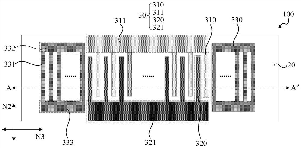
[0052] An embodiment of the present invention provides a resonator device, figure 1 is a schematic structural diagram of a resonant device provided by an embodiment of the present invention, specifically a side view of a wafer-level resonant device, wherein figure 1 The wafer substrate 10 and the piezoelectric layer 20 of the wafer-level resonant device are only schematically shown, and the wafer-level resonant device may include a plurality of resonant devices. figure 1 One of the resonant devices 100 is exempla...


PUM


Abstract

The embodiment of the invention discloses a resonance device and an acoustic filter. The resonance device comprises a wafer substrate, a piezoelectric layer and an interdigital electrode layer. The piezoelectric layer is located on one side of the wafer substrate and comprises a piezoelectric single crystal material, and the piezoelectric single crystal material comprises a first crystal axis, a second crystal axis and a third crystal axis which are perpendicular to one another; the direction of an electric field generated by the interdigital electrode layer in the piezoelectric layer is a device direction; wherein the first crystal axis is perpendicular to the wafer substrate, the included angle between the device direction and the second crystal axis is A1, and A1 is larger than or equal to minus 30 degrees and smaller than or equal to 10 degrees; or, the first crystal axis is perpendicular to the wafer substrate, the included angle between the device direction and the second crystal axis is A2, and A2 is larger than or equal to 170 degrees and smaller than or equal to 210 degrees; or, the included angle between the second crystal axis and the direction perpendicular to the wafer substrate is an angle B1, B1 is larger than or equal to-20 degrees and smaller than or equal to 40 degrees, the included angle between the device direction and the first crystal axis is an angle B2, B2 is larger than or equal to-20 degrees and smaller than or equal to 20 degrees; and the working frequency and the performance of the resonator device are improved while the low manufacturing cost of the resonator device is ensured.

Description

technical field [0001] Embodiments of the present invention relate to the technical field of wireless communication, and in particular, to a resonator device and an acoustic filter. Background technique [0002] As an important part of the wireless communication front-end, radio frequency acoustic filter devices have the functions of frequency selection and suppression of interference signals. A radio-frequency acoustic filter device with better performance can not only improve the sensitivity of the transmitter and reduce the spectrum footprint of the transmitter, but also improve the signal-to-noise ratio of the transceiver and reduce the power consumption of mobile devices in the communication link. Radio frequency acoustic filter devices consist of resonant devices. [0003] Existing resonators are mainly surface acoustic wave resonators (Surface Acoustic Wave, SAW) and bulk acoustic wave resonators (Bulk Acoustic Wave, BAW). SAW resonant devices and BAW resonant devic...

Claims


Application Information

Patent Timeline
IPC IPC(8): H03H9/25H03H9/64
CPCH03H9/25H03H9/64
Inventor 龚颂斌杨岩松
Owner SPECTRON (SHENZHEN) TECH CO LTD
Learn More