A polishing device for metal processing

A polishing device and hardware technology, which is applied in the direction of grinding/polishing safety devices, metal processing equipment, grinding drive devices, etc., can solve problems such as time-consuming, unreachable, and affecting polishing effects, so as to increase the probability of shedding and improve the polishing effect. Remove effects, add effects to fixed effects

Active Publication Date: 2022-06-21
鹤山市波得威卫浴实业有限公司
View PDF0 Cites 0 Cited by
  • Summary
  • Abstract
  • Description
  • Claims
  • Application Information

AI Technical Summary

Problems solved by technology

[0003] In the production process of existing steel balls for bearings, the surface of the steel balls needs to be polished to reduce the friction between the steel balls and the bearing ring. Among the existing steel ball polishing methods, drum polishing is the most commonly used polishing method. Put the steel ball and polishing material directly in the drum, and then use the motor to drive the drum to rotate, and use the friction between the steel ball and the polishing material to polish the steel ball. After polishing, some iron powder will adhere to the polishing material. Timely removal will cause friction between the iron powder and the steel ball during the polishing process, which will cause scratches on the surface of the steel ball and affect the polishing effect
The existing iron powder removal technology is to directly take out the polishing material, and then directly use a magnet to adsorb the iron powder, but this technology will not only consume a lot of time, but also easily cause the iron powder to move from a part of the polishing material to another Part of the polishing material, the removal effect is poor, and the expected effect cannot be achieved

Method used


Image

  • A polishing device for metal processing
  • A polishing device for metal processing
  • A polishing device for metal processing

Examples


Embodiment Construction

[0031] The technical solutions in the embodiments of the present invention will be clearly and completely described below with reference to the accompanying drawings in the embodiments of the present invention. Obviously, the described embodiments are only a part of the embodiments of the present invention, rather than all the embodiments. Based on the embodiments of the present invention, all other embodiments obtained by those of ordinary skill in the art without creative efforts shall fall within the protection scope of the present invention.

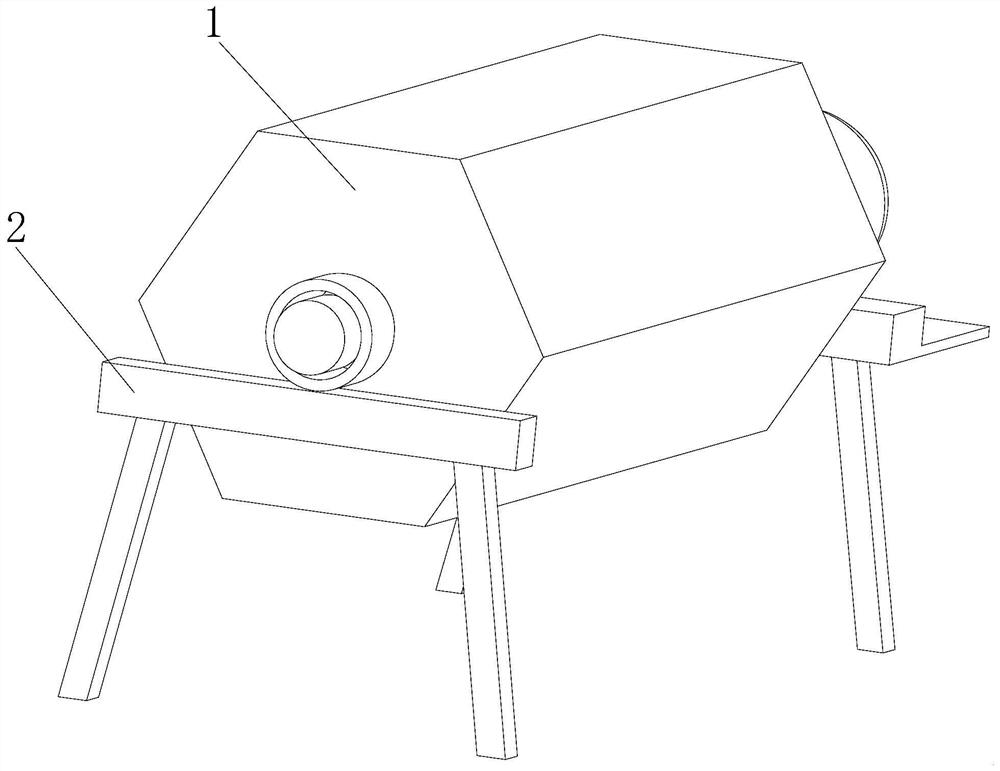
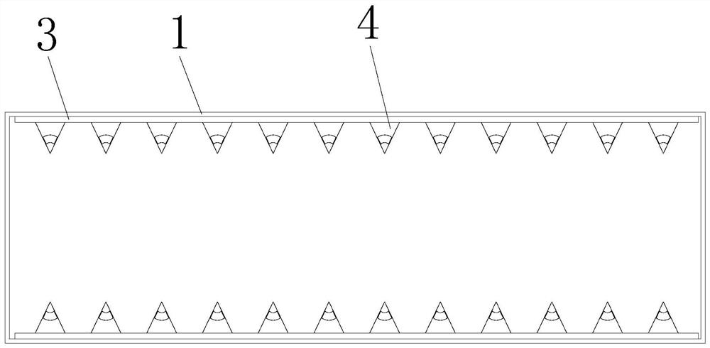
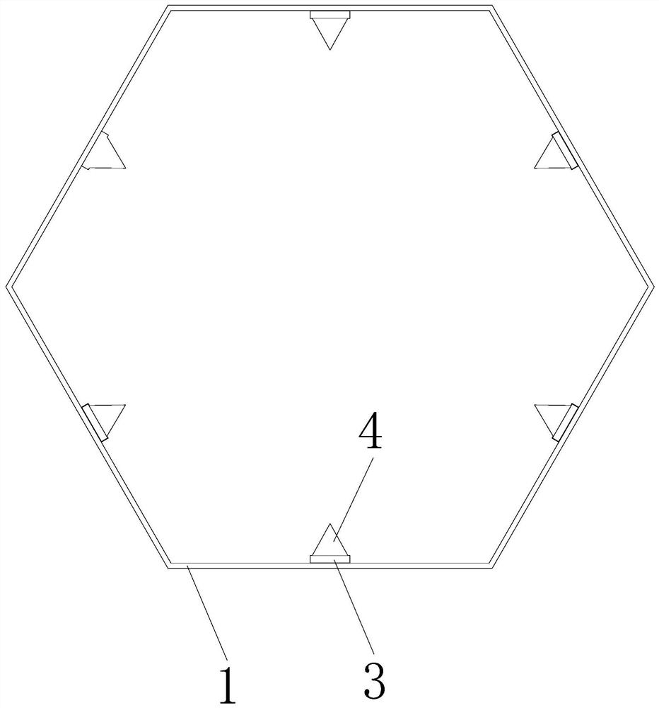
[0032] see Figure 1-9, the present invention provides a technical solution: a polishing device for hardware processing, comprising a drum 1, both ends of the drum 1 are fixed on a bracket 2, a plurality of storage bins 3 are fixedly installed on the inner wall of the drum 1, and the inner wall of the storage bin 3 is installed with Magnetic strips 31, a collection block 4 is fixedly installed on one side of the storage bin 3, a flow...


PUM


Abstract

The invention discloses a polishing device for metal processing, which relates to the technical field of hardware processing. The polishing device for hardware processing includes a roller, the two ends of the roller are fixed on the bracket, the inner wall of the roller is fixedly installed with a plurality of storage bins, the inner wall of the storage bin is installed with a magnetic strip, and one side of the storage bin is fixedly installed There is a collection block, a flow channel is opened between the two sides of the collection block, the bottom of the flow channel communicates with the inside of the storage bin through the absorption channel, and the part of the collection block between the flow channel and the storage bin is opened with a Two sets of cavity one and cavity two. The polishing device for hardware processing collects the iron powder on the surface of the polishing material through the collecting block during the polishing process, and the polishing material passes through the flow channel in sequence, so that the iron powder on the surface of a part of the polishing material does not move to another when the iron powder is removed. The condition of a part of the surface of the polishing material, thereby improving the removal effect and efficiency of iron powder on the surface of the polishing material.

Description

technical field [0001] The invention relates to the technical field of hardware processing, in particular to a polishing device for hardware processing. Background technique [0002] Hardware: Traditional hardware products, also known as "small hardware". Refers to the five metals of gold, silver, copper, iron and tin. After manual processing, it can be made into art or metal devices such as knives and swords. Hardware in modern society is more extensive, such as hardware tools, hardware parts, daily hardware, construction hardware and security supplies. Most hardware products are not final consumer goods. Steel balls are divided into grinding steel balls, forging steel balls and casting steel balls according to the production and processing technology. According to the processing material, it is divided into bearing steel balls, stainless steel balls, carbon steel balls, copper bearing steel balls, alloy steel balls, etc. Among them, the bearing steel ball is an importa...

Claims


Application Information

Patent Timeline
Patent Type & Authority Patents(China)
IPC IPC(8): B24B31/03B24B31/12B24B55/06B24B55/12B24B47/00
CPCB24B31/03B24B31/12B24B55/06B24B55/12B24B47/00
Inventor 俞文君
Owner 鹤山市波得威卫浴实业有限公司
Why Eureka
Try Eureka