
Dynamic self-adaptive SOC system working in sub-threshold region and adjusting method

A dynamic self-adaptive, sub-threshold technology, applied in the direction of measuring devices, instruments, measuring electronics, etc., can solve the problems of digital SOC circuit not working and affecting the performance parameters of digital SOC circuit, so as to improve the production yield and overcome the effect of failure

Pending Publication Date: 2021-06-04
浙江聚芯集成电路有限公司
View PDF0 Cites 0 Cited by
  • Summary
  • Abstract
  • Description
  • Claims
  • Application Information

AI Technical Summary

Problems solved by technology

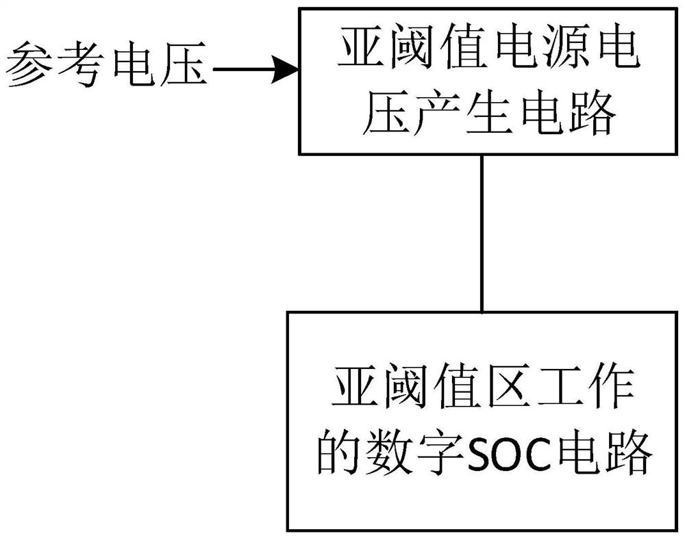
[0004] The purpose of the present invention is to overcome the shortcoming of prior art, provide a kind of dynamic self-adaptive SOC system and adjustment method that keep working in the sub-threshold area, solve the existing digital SOC circuit can not work in the best state and, thus affect the digital SOC The performance parameters of the circuit even lead to the problem that the digital SOC circuit cannot work

Method used


Image

  • Dynamic self-adaptive SOC system working in sub-threshold region and adjusting method
  • Dynamic self-adaptive SOC system working in sub-threshold region and adjusting method
  • Dynamic self-adaptive SOC system working in sub-threshold region and adjusting method

Examples


Embodiment 1

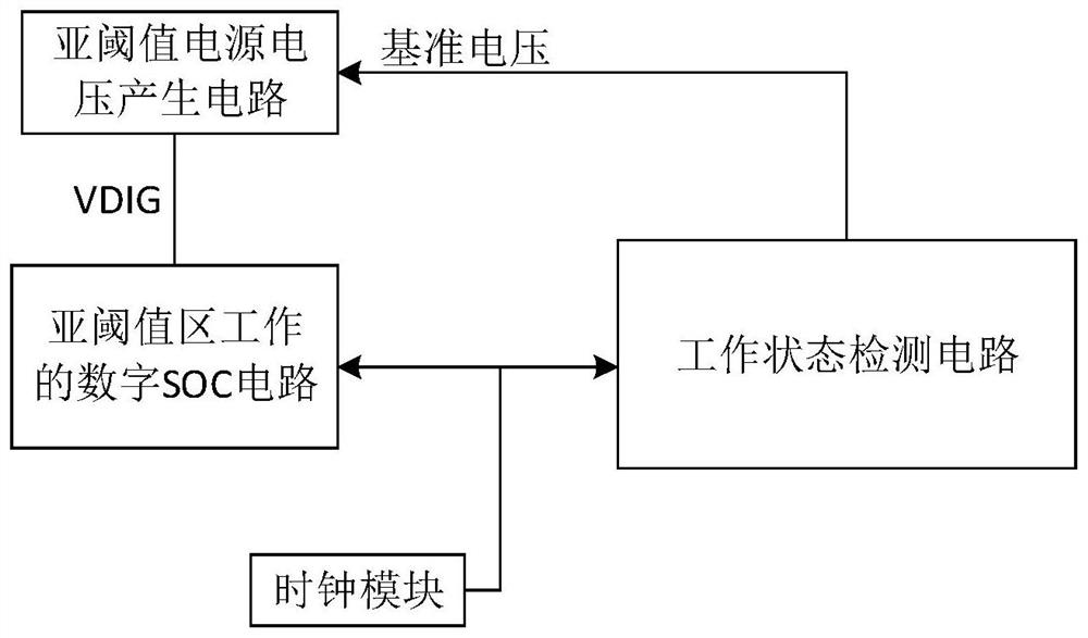
[0033] Example 1, such as figure 2 As shown, it includes a sub-threshold power supply voltage generation circuit, a working state detection circuit, a digital SOC circuit and a clock module; the working state detection circuit is connected to the digital SOC circuit, and the working state detection circuit outputs a reference voltage to The input end of the sub-threshold power supply voltage generation circuit; the voltage output end of the sub-threshold power supply voltage generation circuit is connected to the input end of the digital SOC circuit; the clock module is respectively connected to the working state detection circuit and the digital SOC The clock side of the circuit is connected.

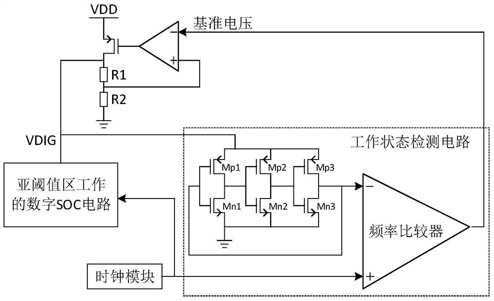
[0034] Further, the sub-threshold power supply voltage generation circuit includes a linear voltage regulator; the output terminal of the linear voltage regulator is connected to the gate of a mos tube, the drain of the mos tube is connected to the ground after two resistors are conne...

Embodiment 2

[0038] Example 2, such as image 3 As shown, the difference between this embodiment and Embodiment 1 lies in the working state detection circuit; in this embodiment, the working state detection circuit includes a frequency discriminator, a low-pass filter and a voltage-controlled delay unit circuit; the output terminals of the clock module are respectively It is connected with the frequency discriminator and the voltage-controlled delay unit circuit; the output end of the frequency discriminator is connected with the low-pass filter; the output end of the voltage-controlled delay unit circuit is connected with the frequency discriminator ; The output voltage of the low-pass filter is sent to the negative input terminal of the voltage-controlled delay unit circuit and the linear voltage regulator.

[0039] Further, the voltage-controlled delay unit circuit comprises a plurality of delay units connected in series, the low-pass filter outputs a voltage to each delay unit, the clo...


PUM


Abstract

The invention relates to a dynamic self-adaptive SOC system working in a sub-threshold region and an adjusting method. The dynamic self-adaptive SOC system comprises a sub-threshold power supply voltage generation circuit, a working state detection circuit, a digital SOC circuit and a clock module; the clock module outputs the same clock or frequency to the working state detection circuit and the digital SOC circuit, the working state detection circuit compares the fed-back clock or frequency in real time to dynamically and adaptively adjust a reference circuit output to the sub-threshold power supply voltage generation circuit, and then voltage input to the digital SOC circuit is adjusted, and therefore, the system works in the sub-threshold region. According to the invention, dynamic self-adaptive adjustment is realized, the production yield is improved, and meanwhile, the failure caused by an unpredictable working environment is overcome.

Description

technical field [0001] The invention relates to the technical field of integrated circuit SOC, in particular to a dynamic self-adaptive SOC system and an adjustment method that keep working in a sub-threshold region. Background technique [0002] With the rise of IOT, the demand for ultra-low power SOC (system-on-chip) is getting stronger and stronger. A common way to achieve ultra-low power consumption is to make the SOC work in the sub-threshold region. In order to make the system work in the sub-threshold region, it is only necessary to reduce the power supply voltage of the system to near the sub-threshold value. Because the system works in the sub-threshold region, the reliability of the circuit is greatly reduced, and a large number of experiments are usually required to try the appropriate power supply voltage. However, due to the fact that the process parameters in the chip manufacturing process are not completely determined according to a certain statistical distrib...

Claims


Application Information

Patent Timeline
Patent Type & Authority Applications(China)
IPC IPC(8): G01R31/36
CPCG01R31/36
Inventor 职春星郑剑钦赵明
Owner 浙江聚芯集成电路有限公司
Learn More