
Air tightness detection system and air tightness detection method

An air tightness detection and detection technology, which is applied in the detection field, can solve problems such as difficult to detect the air tightness of the equipment to be tested, unstable gas pressure, and non-compliance of air tightness

Inactive Publication Date: 2021-06-04
CHNA ENERGY INVESTMENT CORP LTD +2
View PDF6 Cites 1 Cited by
  • Summary
  • Abstract
  • Description
  • Claims
  • Application Information

AI Technical Summary

Problems solved by technology

[0003] For some special components, especially the detection of solid fuel cells and sealing materials and gas distribution plates in fuel cell systems, the ambient temperature around them may change from low or normal temperature to high during use, and may There will be situations where the airtightness is good and meets the regulations at room temperature, but at high temperatures due to various factors such as material expansion and deformation, the airtightness is not in compliance. Therefore, the airtightness test under high temperature conditions is very necessary. Yes, but the existing relevant air tightness testing equipment does not take into account that under high temperature conditions, there will be strong convection formed by the action of high temperature gas and low temperature gas, making the gas pressure unstable and resulting in unreliable test results. Existing air tightness detection systems are difficult to detect the air tightness of the equipment to be tested under high temperature conditions

Method used


Image

  • Air tightness detection system and air tightness detection method
  • Air tightness detection system and air tightness detection method
  • Air tightness detection system and air tightness detection method

Examples


Embodiment Construction

[0022] The specific implementation manners of the embodiments of the present invention will be described in detail below in conjunction with the accompanying drawings. It should be understood that the specific implementation manners described here are only used to illustrate and explain the embodiments of the present invention, and are not intended to limit the embodiments of the present invention.

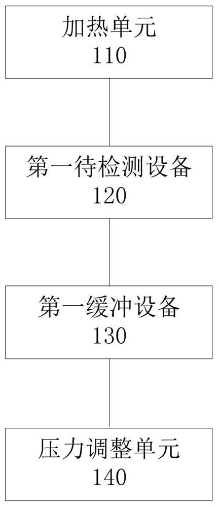
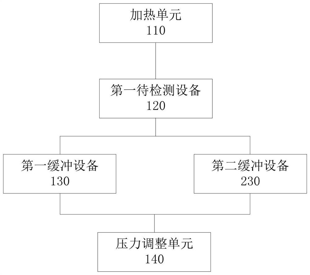
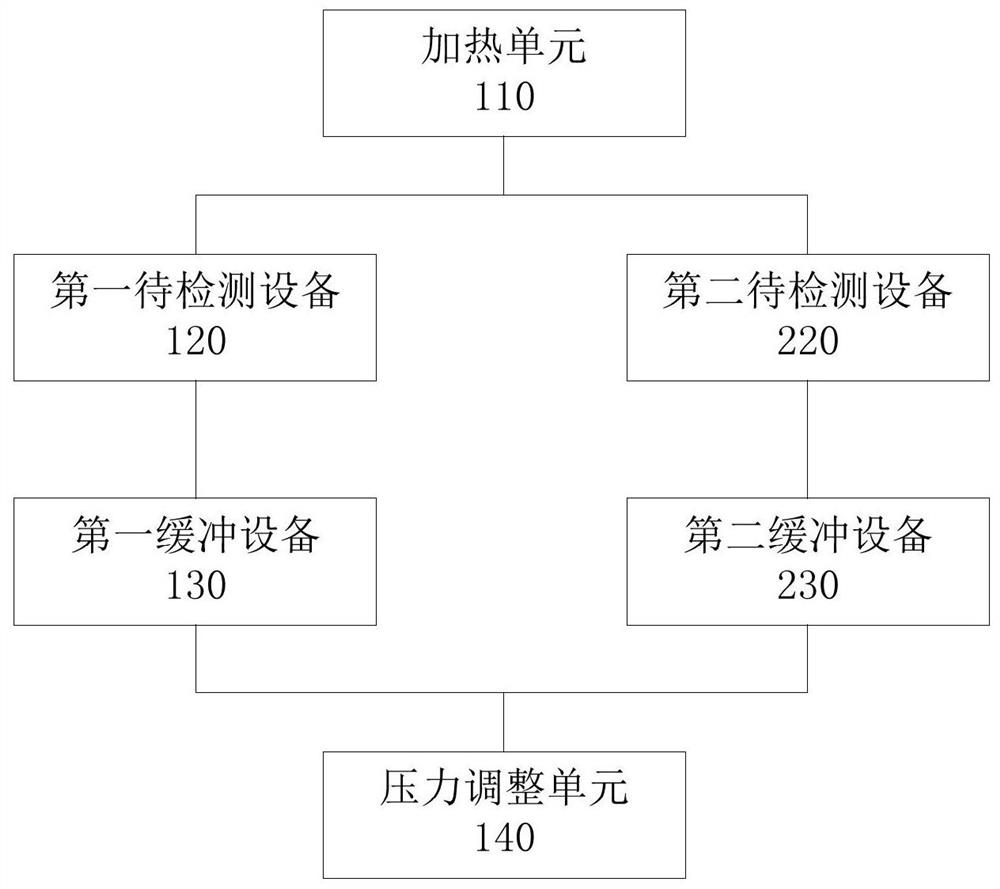
[0023] figure 1 It is a structural block diagram of the air tightness detection system provided by the first embodiment of the present invention. Such as figure 1 As shown, the air tightness testing system includes: a heating unit 120 for heating the first device to be tested 110; a first buffer device 130 connected to the first device to be tested 110 through a first pipeline; pressure adjustment The unit 140 is connected with the first buffer device 130 through a second pipeline. Wherein, the air tightness detection system provided by the embodiment of the present invention a...


PUM

PropertyMeasurementUnit
Diameteraaaaaaaaaa

Abstract

The embodiment of the invention provides an air tightness detection system and an air tightness detection method, and belongs to the technical field of detection. The air tightness detection system comprises a heating unit used for heating a first device to be detected, a first buffer device, and a second buffer device, one end of the first buffer device is connected with a first end of the first device to be detected through a first pipeline; a first pressure detection unit used for detecting the pressure in the first pipeline; and a pressure adjusting unit connected with the other end of the first buffer device through a second pipeline, wherein the first buffer device is used for preventing convection between the first pipeline and the second pipeline. According to the technical scheme provided by the invention, the problem of unstable pressure caused by severe convection between high-temperature gas and low-temperature gas can be prevented by adopting the first buffer device, so that the accuracy and the reliability of a test result of an air tightness detection test under a high-temperature condition can be improved.

Description

technical field [0001] The invention relates to the technical field of detection, in particular to an airtightness detection system and an airtightness detection method. Background technique [0002] The air tightness detection system is widely used in the leakage detection in the production process of aerospace, automobiles, gas appliances and other parts. For example, it can detect the leakage of sealing materials and gas distribution plates in solid fuel cells and fuel cell systems under normal temperature conditions. air tightness. [0003] For some special components, especially the detection of solid fuel cells and sealing materials and gas distribution plates in fuel cell systems, the ambient temperature around them may change from low or normal temperature to high during use, and may There will be situations where the airtightness is good and meets the regulations at room temperature, but at high temperatures due to various factors such as material expansion and def...

Claims


Application Information

Patent Timeline
IPC IPC(8): G01M3/26
CPCG01M3/26
Inventor 张颖张宇琼李轩由晓彬郭强
Owner CHNA ENERGY INVESTMENT CORP LTD
Learn More