
A turbine blade with bolt-on ceramic armor

A turbine blade, fixed technology, applied in the direction of blade support components, machines/engines, mechanical equipment, etc., can solve the problems of low cooling effect and large cooling air consumption

Active Publication Date: 2022-03-29
DALIAN UNIV OF TECH
View PDF10 Cites 0 Cited by
  • Summary
  • Abstract
  • Description
  • Claims
  • Application Information

AI Technical Summary

Problems solved by technology

However, with the further increase of the turbine intake temperature of the next-generation engine, this type of structure has exposed the shortcomings of low cooling effect and large cooling air consumption, which can no longer meet the requirements. There is an urgent need to improve the blade cooling structure and reduce the cooling air consumption.

Method used


Image

  • A turbine blade with bolt-on ceramic armor
  • A turbine blade with bolt-on ceramic armor
  • A turbine blade with bolt-on ceramic armor

Examples


Embodiment 1

[0022] In order to make the content of the present invention more clearly understood, the present invention will be further described in detail below based on specific embodiments and in conjunction with the accompanying drawings.

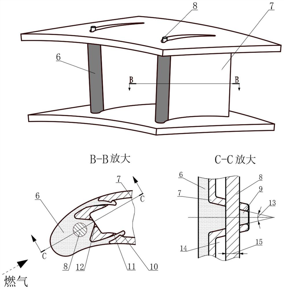
[0023] see figure 2 As shown, this embodiment is a turbine blade using a bolt-fixed ceramic armor, which is composed of a leading edge 6 of a ceramic matrix composite material, a metal matrix 7, and a fixed bolt 8. The leading edge 6 of ceramic matrix composite material is made of ceramic matrix composite material, and the metal matrix 7 and the fixing pin 8 are both made of superalloy. During use, insert the pin hole on the ceramic armor and the metal substrate 7 simultaneously, make the two be connected and fixed. In order to install smoothly and ensure the structure is firm enough, the fixed pin diameter φD 1 Be 1.6mm, the orientation of the ceramic armor pinhole boss 9 is parallel to the gas direction. Pin hole boss wedge angle ∠θ 1 = 16°....

Embodiment 2

[0025] Such as Figure 4 As shown, this embodiment is a turbine blade that adopts a fixed ceramic armor with offset pins. In this embodiment, the position of the fixed pin 8 is offset. Among them, 6 parts of the front edge of the ceramic matrix composite material are provided with semi-square pin holes, while 7 parts of the metal matrix are provided with complete square pin holes. The offset square fixed bolt 16 is the main stress-bearing part. In order to ensure reliability, 17. The side length of the offset square fixed pin is L=1.2mm, and the angle of the boss of the ceramic armor pin hole is parallel to the gas direction. Pin hole boss wedge angle side length ∠θ 1 = 12°.


PUM


Abstract

The invention belongs to the technical field of aero-engine turbine blades, and relates to a turbine blade adopting a bolt-fixed ceramic armor. The structural scheme of the present invention is aimed at the leading edge area of ​​the turbine blade, which can realize the fast and stable connection between the ceramic matrix composite material component and the metal matrix of the blade, and effectively protect the leading edge area of ​​the turbine blade without destroying the original aerodynamic appearance of the blade And reduce the use of cooling gas to improve the high temperature resistance of the blades, as well as the thrust performance of the engine. At the same time, after the ceramic armor is damaged, it can be easily replaced during maintenance, and the high-value blade metal substrate can be reused to prolong its life, thereby greatly improving the economy of engine use and maintenance.

Description

technical field [0001] The invention belongs to the technical field of aero-engine turbine blades, and relates to a turbine blade adopting a bolt-fixed ceramic armor. Background technique [0002] For an aero turbine engine, an increase in the gas temperature before the turbine means an increase in engine thrust and performance. On the basis of the existing 1500°C level, if the turbine intake temperature increases by 100°C, the thrust of the engine can be increased by more than 10%. According to predictions, the temperature before the turbine of advanced aero-engines in the future may exceed 1800°C, which is much higher than the safe working temperature of known superalloys and the cooling capacity of conventional cooling measures. For this reason, solving the problem of insufficient temperature bearing capacity of turbine blades is the key to the development of high thrust-to-weight ratio aeroengines. For the turbine guide vanes, the leading edge part directly bears the i...

Claims


Application Information

Patent Timeline
Patent Type & Authority Patents(China)
IPC IPC(8): F01D5/14F01D5/28F01D5/18
CPCF01D5/14F01D5/147F01D5/282F01D5/284F01D5/18
Inventor 吕东刘永泉梁彩云孙智强王楠孙一楠
Owner DALIAN UNIV OF TECH
Learn More